Follow-up vision system optical axis and rotating shaft deviation calibration and external parameter correction method
A vision system and correction method technology, applied in the field of computer vision, can solve the problems of inability to realize online real-time external parameter correction and inability to guarantee accuracy.
- Summary
- Abstract
- Description
- Claims
- Application Information
AI Technical Summary
Problems solved by technology
Method used
Image

Examples
Embodiment Construction
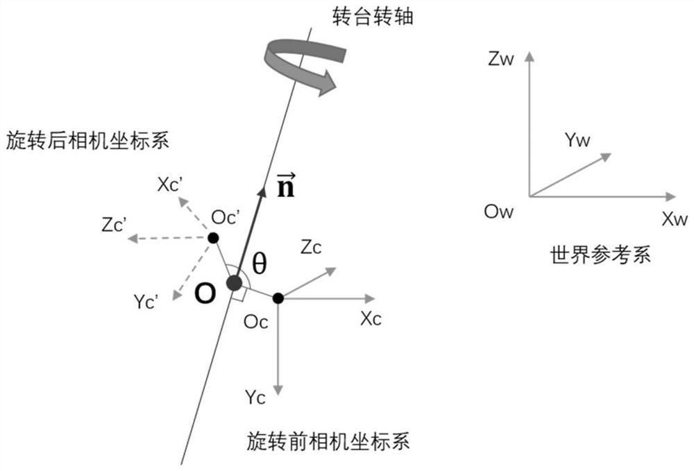
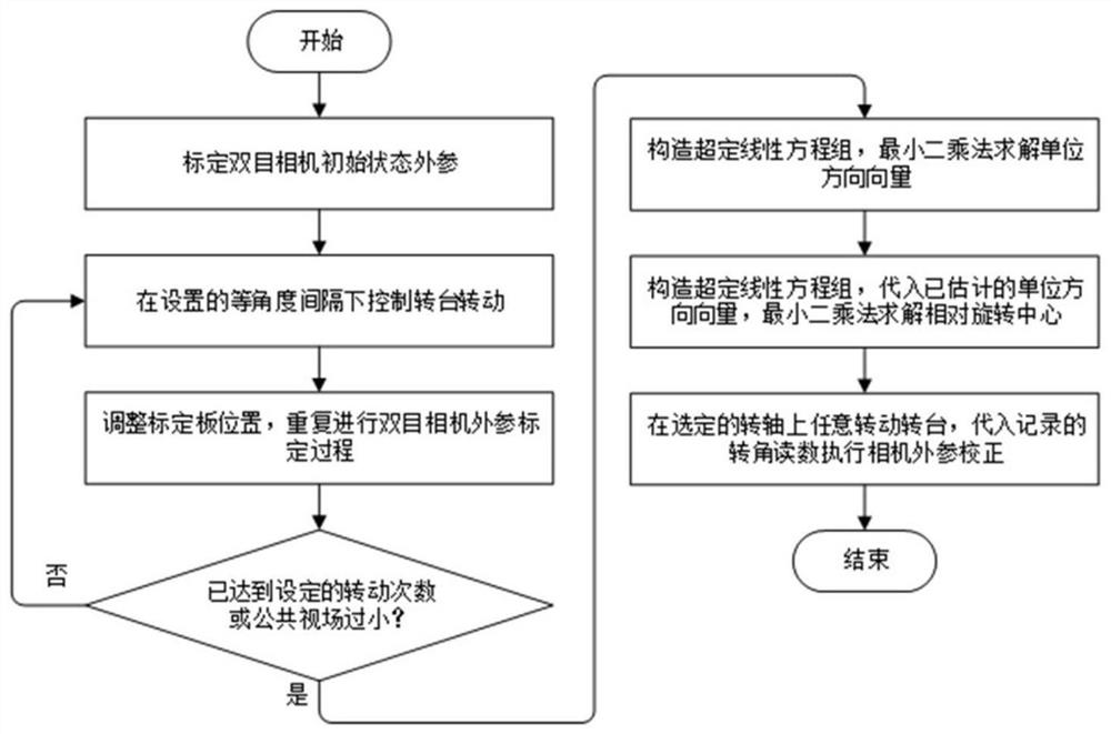
[0067] Such as figure 1 , 3 As shown, a method for calibrating the deviation between the optical axis and the rotating shaft of the follow-up vision system and correcting the external parameters, the method includes the steps in the following order:
[0068] (1) In the world coordinate system O w -X w Y w Z w Next, establish the optical center position of the camera before rotation O c According to the mathematical expression of the equivalence, the optical center position of the camera after rotation is established in the camera coordinate system before rotation O c the mathematical expression of
[0069] (2) According to the equivalence of the rotation axis of the turntable in geometric space and algebraic space, select one of the rotation axes, and define the deviation parameter of the rotation axis relative to the optical center of the camera in the world coordinate system, including the unit of the rotation axis direction vector The coordinate vector correspondin...
PUM
 Abstract
Description
Claims
Application Information