Heat dissipation device used in cooperation with power transformer

A technology for power transformers and heat dissipation devices, applied in the direction of transformer/inductor cooling, etc., can solve problems such as poor practicability and inability to achieve technological breakthrough innovations, and achieve the effect of improving heat dissipation efficiency

Pending Publication Date: 2020-12-08
SHENYANG TIANTONG ELECTRICITY
View PDF3 Cites 2 Cited by
  • Summary
  • Abstract
  • Description
  • Claims
  • Application Information

AI Technical Summary

Problems solved by technology

By searching the content of the file, we can see that its practicability is not strong, and it cannot achieve technological breakthrough innovation in this field

Method used


Image

  • Heat dissipation device used in cooperation with power transformer
  • Heat dissipation device used in cooperation with power transformer
  • Heat dissipation device used in cooperation with power transformer

Examples


Embodiment Construction

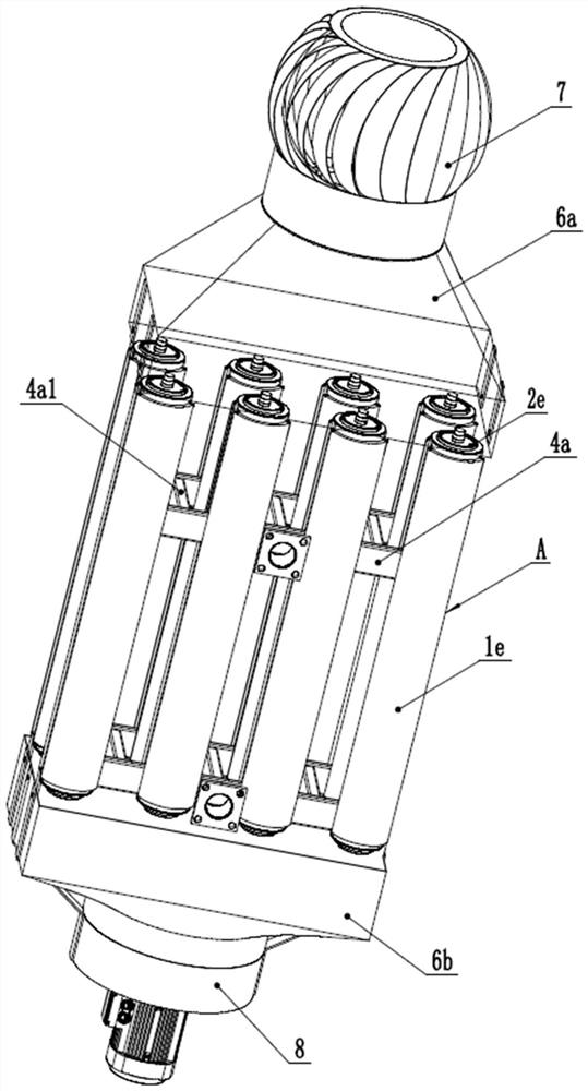
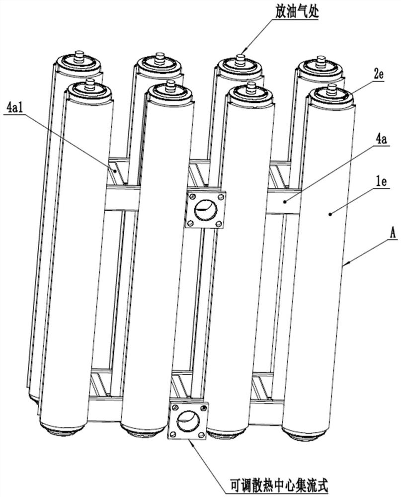
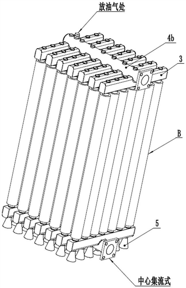
[0048] The heat dissipation device used in conjunction with this power transformer includes a heat dissipation unit, a heat dissipation unit, a heat dissipation assembly, a ventilation component, and a PLC fan control unit. The heat dissipation assembly is made of aluminum alloy, copper, and steel, and the heat dissipation medium includes transformer oil. , Sulfur hexafluoride gas, the inlet and outlet flanges are connected to the heat dissipation medium pipeline of the transformer, which is characterized in that the inner pipe and the outer pipe are set together to form a multi-layer cavity A type, B type heat dissipation unit, and the junction box 3 is composed The heat dissipation unit, the heat dissipation unit and the three kinds of collectors 4b~4d form a heat dissipation assembly, which constitutes a central collection type and a peripheral collection type heat dissipation assembly. The difference is that the adjustable heat dissipation center type heat dissipation The c...


PUM


Abstract

A heat dissipation device used in cooperation with a power transformer is characterized in that an inner pipe and an outer pipe in a heat dissipation body are sleeved to form a plurality of A-type heat dissipation single bodies and B-type heat dissipation single bodies of an interlayer cavity structure, heat media in a transformer oil tank circulate in interlayer cavities, and heat dissipation fins or spiral heat dissipation fins are evenly distributed on the inner wall of the inner pipe and the outer wall of the outer pipe of each heat dissipation single body in the axial or radial direction;and the B-type heat dissipation single bodies and a confluence box form a heat dissipation unit, the heat dissipation unit and the flow collecting pipe form a heat dissipation combination body, the heat dissipation combination body can be divided into an adjustable heat dissipation center flow collecting type, a center flow collecting type and a peripheral flow collecting type according to the flow collecting type, and an unpowered air inducer is installed on the upper portion of the heat dissipation combination body for ventilation. The self-cooling effect and the heat dissipation efficiencyof the heat dissipation device are remarkably improved, the running temperature of the transformer is effectively reduced, the insulation and aging resistance of the transformer are protected, the heat dissipation device replaces or reduces fans, the heat dissipation device is an effective scheme for realizing energy conservation, and meanwhile, the manufacturing cost of the current heat dissipation device is also reduced.

Description

technical field [0001] The invention belongs to the field of processing, and relates to a cooling device used in conjunction with a power transformer. Background technique [0002] At present, the design and manufacture of power transformers have entered the stage of high-end and high-quality development. The supporting heat dissipation devices such as fin radiators and strong oil air coolers have not achieved new technological breakthroughs and innovations in the industry for decades. Its high manufacturing cost and low heat dissipation performance have become one of the main bottlenecks in the transformer industry. The industry has made some new technical solutions for this, such as retrieval 1, CN201110410625.1 High-frequency water-cooled transformer based on aluminum profile radiator, transformer secondary The winding and the center tap terminal are fixed on the aluminum radiator through the copper sleeve and the manifold. However, the defect of this scheme is poor stre...

Claims


Application Information

Patent Timeline
IPC IPC(8): H01F27/08
CPCH01F27/08
Inventor 王天林曲寿晴万成姜洪强
Owner SHENYANG TIANTONG ELECTRICITY
Why Eureka
Try Eureka