
Front-end structure of spindle and electric spindle

A technology of spindle front end and electric spindle, which is applied in the direction of large fixed members, metal processing machinery parts, maintenance and safety accessories, etc., can solve the problems of poor lubrication effect of front support bearing parts, and achieve the effect of ensuring work reliability

Inactive Publication Date: 2020-12-11
GREE ELECTRIC APPLIANCES INC
View PDF6 Cites 4 Cited by
  • Summary
  • Abstract
  • Description
  • Claims
  • Application Information

AI Technical Summary

Problems solved by technology

[0003] Therefore, the technical problem to be solved by the present invention is that the existing electric spindle for deep cavity processing has poor lubrication effect of the front support bearing, thereby providing a spindle front end structure and electric spindle

Method used


Image

  • Front-end structure of spindle and electric spindle
  • Front-end structure of spindle and electric spindle
  • Front-end structure of spindle and electric spindle

Examples


Embodiment Construction

[0036] In order to make the purpose, technical solution and advantages of the present invention clearer, the technical solution of the present invention will be clearly and completely described below in conjunction with specific embodiments of the present invention and corresponding drawings. Apparently, the described embodiments are only some of the embodiments of the present invention, but not all of them. Based on the embodiments of the present invention, all other embodiments obtained by persons of ordinary skill in the art without making creative efforts belong to the protection scope of the present invention.

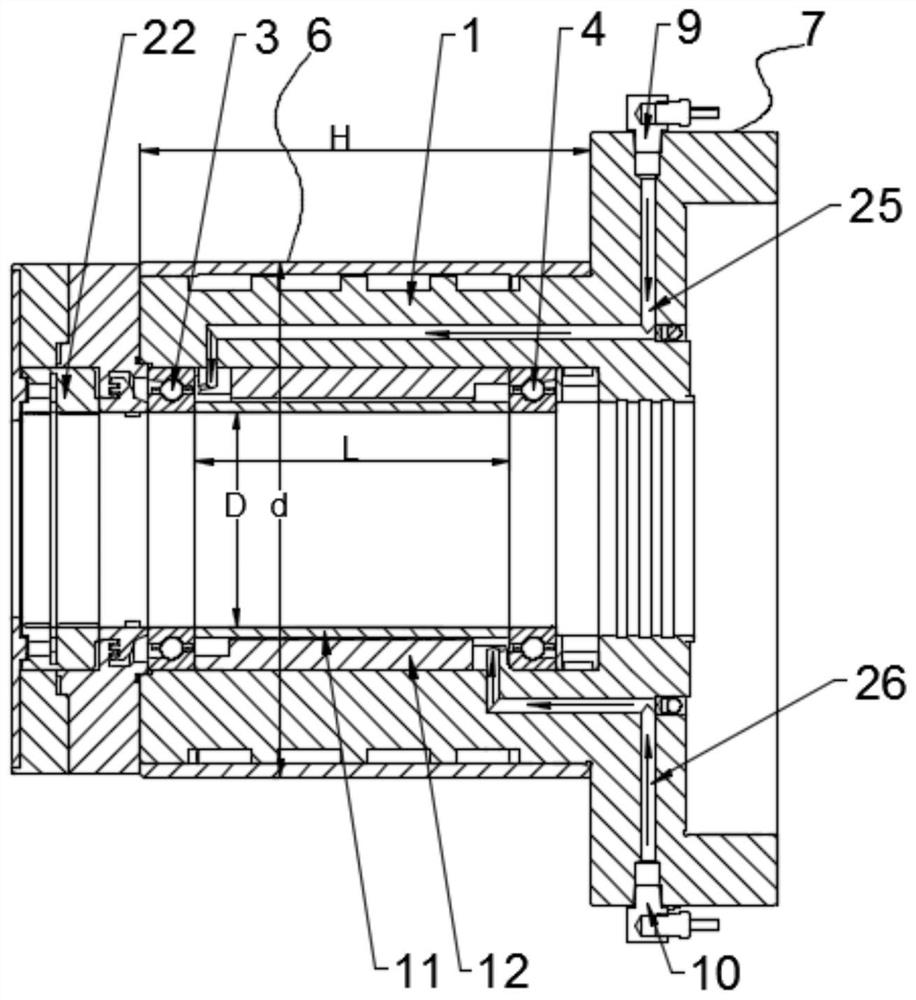
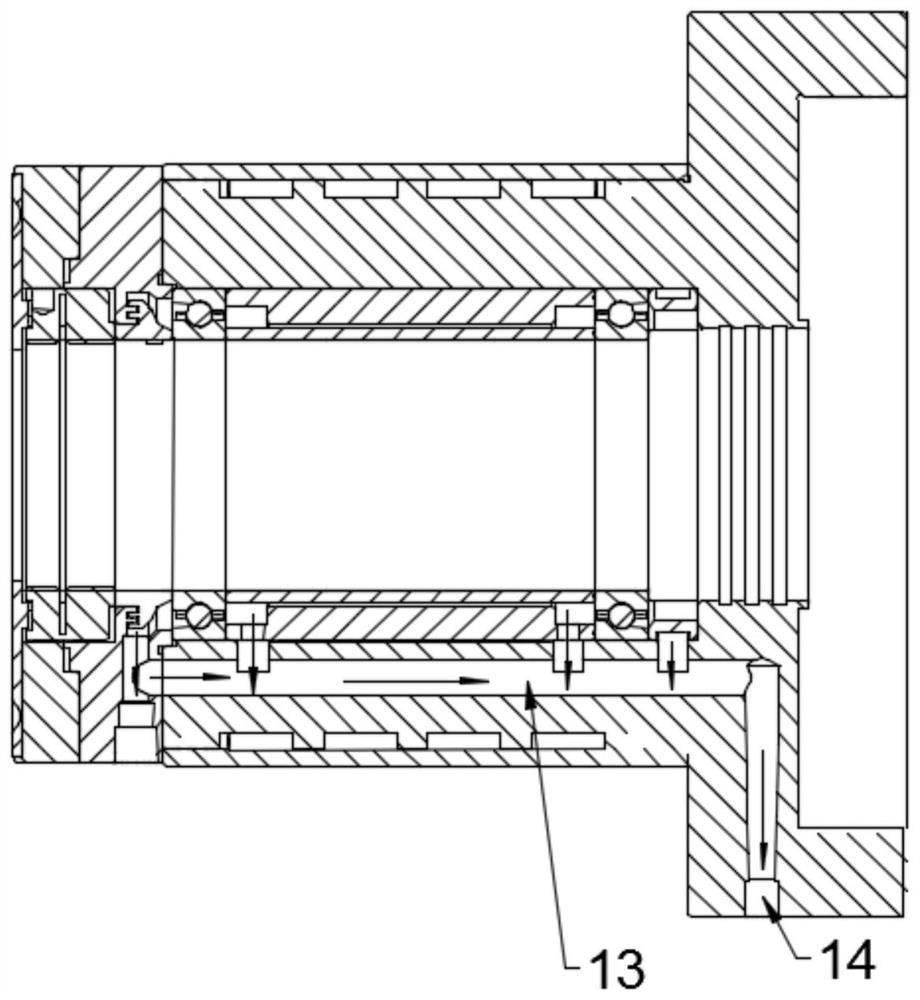
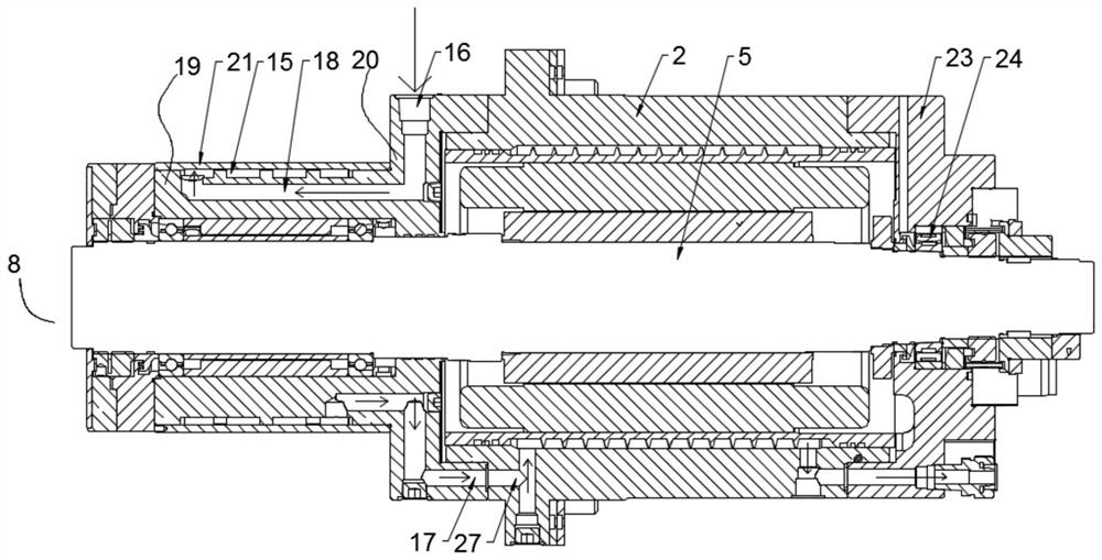
[0037] combine Figure 1-3 As shown, a spindle front end structure disclosed in this embodiment is installed at the end of the motor main body 2 of the electric spindle, including: a front end main body 1 connected to the motor main body 2; at least one first front bearing 3, at least one A second front bearing 4, at least one first front bearing 3, and at least ...


PUM


Abstract

The invention provides a front-end structure of a spindle and an electric spindle. The front-end structure of the spindle is mounted on an end part of a motor main body of the electric spindle and comprises a front-end main body connected to the motor main body, at least one first front bearing and at least one second front bearing which are axially mounted in the front-end main body in a spaced manner for supporting a central spindle part of the electric spindle, a first lubricating path arranged on the front-end main body for conveying a lubricating liquid to the at least one first front bearing and a second lubricating pat arranged on the front-end main body for conveying a lubricating liquid to the at least one second front bearing. According to the front-end structure of the spindle,independent oil-gas lubrication is provided to different front bearings through different lubricating paths, and the lubricating liquid is fed to the front bearings in different positions more precisely according to a rotating speed and a machining environment of the spindle to ensure that the different front bearings are lubricated precisely, so that the working reliability of the electric spindle is guaranteed.

Description

technical field [0001] The invention belongs to the technical field of electric spindles, and in particular relates to a spindle front end structure and an electric spindle. Background technique [0002] At present, most of the high-speed vertical machining electric spindles are aimed at plane milling, and there are few deep-cavity machining electric spindles that are specially designed for difficult machining such as molds. The mold material has the characteristics of high strength and rigidity, which makes it difficult to process, and the extension part is generally inside the cavity. The existing electric spindle structure adopts a front end structure with a large aspect ratio, and at the same time increases the span of the front support bearing , leading to differences in the lubrication requirements of the front support bearings, the existing lubrication ignores this difference, which will adversely affect the service life and machining accuracy of the spindle. Conten...

Claims


Application Information

Patent Timeline
IPC IPC(8): B23B19/02B23Q11/12
CPCB23Q1/70B23Q11/123B23Q11/127
Inventor 胡余生崔中张廷开刘永连何圳涛
Owner GREE ELECTRIC APPLIANCES INC
Learn More