
Following type wood laser cutting and polishing device

A laser cutting and wood technology, applied in the direction of grinding drive device, grinding/polishing safety device, laser welding equipment, etc., can solve the problems of fire and blackening of cut wood, achieve high processing efficiency, maintain the processing environment, reduce The effect of fire risk

Inactive Publication Date: 2020-12-11
FUZHOU JINAN BAXIAN TECH CO LTD
View PDF0 Cites 0 Cited by
  • Summary
  • Abstract
  • Description
  • Claims
  • Application Information

AI Technical Summary

Problems solved by technology

[0002] Optical cutting is to use a focused high-power density laser beam to irradiate the workpiece, so that the irradiated material is rapidly melted, vaporized, ablated or reached the ignition point, and at the same time, the molten material is blown away by the high-speed airflow coaxial with the beam, so as to realize the cutting of the workpiece. Open, the use of laser cutting wood has the advantages of high precision, narrow kerf, fast speed, and smooth cutting surface. However, because the laser focused energy melts the wood, there will be blackening during the cutting process, that is, the cutting edge is carbonized Yes, and during processing, cutting wood has a risk of fire due to the high energy of the laser

Method used


Image

  • Following type wood laser cutting and polishing device
  • Following type wood laser cutting and polishing device
  • Following type wood laser cutting and polishing device

Examples


Embodiment Construction

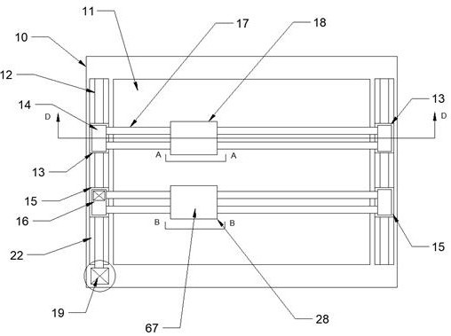
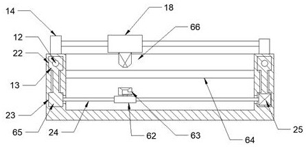
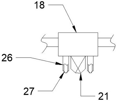
[0021] Combine below Figure 1-8 The present invention is described in detail, wherein, for the convenience of description, the orientations mentioned below are defined as follows: figure 1 The up, down, left, right, front and back directions of the projection relationship itself are the same.

[0022] A follow-up laser cutting and polishing wood device described in conjunction with accompanying drawings 1-8 includes a cutting base 10, a working chamber 11 is provided inside the cutting base 10, and a fixing plate 64 is provided on the rear side of the working chamber 11. The fixing plate 64 is provided with a through hole, the cutting base 10 is symmetrically provided with a longitudinal sliding chamber 22, and the front side of the left longitudinal sliding chamber 22 is threadedly provided with a power slider 13, and the longitudinal sliding chamber 22 is arranged up and down. The wall body is rotated to be provided with a power threaded shaft 12, and the longitudinal slid...


PUM


Abstract

The invention discloses a following type wood laser cutting and polishing device. The following type wood laser cutting and polishing device comprises a cutting base body, wherein a working cavity isformed in the cutting base body; a fixing plate is arranged on the rear side of the working cavity; a through hole is formed in the fixing plate; longitudinal sliding cavities are formed in the cutting base body in a bilateral symmetry mode; power sliding blocks are arranged on the front sides of the longitudinal sliding cavities on the left side in a threaded connection mode; power threaded shafts are rotationally arranged on the upper and lower wall bodies of the longitudinal sliding cavities; and supporting sliding blocks are arranged, on the lower sides of the power sliding blocks, in thelongitudinal sliding cavities. By means of the device, gas for isolating air is released at the laser cutting position, so that the fire risk is reduced. A polishing device follows the rear side of the device, so that carbon black generated by laser can be polished away, a user can freely adjust and remove the side edge of the carbon black according to needs, a good processing surface of wood is guaranteed, and the processing efficiency is high. The lower side of the device is provided with a dust and smoke suction device in a following mode, so that the good processing environment is kept, and dust and smoke are prevented from threatening the health of operators.

Description

technical field [0001] The invention relates to a device for following laser cutting and polishing wood, and mainly relates to the related field of laser cutting. Background technique [0002] Optical cutting is to use a focused high-power density laser beam to irradiate the workpiece, so that the irradiated material is rapidly melted, vaporized, ablated or reached the ignition point, and at the same time, the molten material is blown away by the high-speed airflow coaxial with the beam, so as to realize the cutting of the workpiece. Open, the use of laser cutting wood has the advantages of high precision, narrow kerf, fast speed, and smooth cutting surface. However, because the laser focused energy melts the wood, there will be blackening during the cutting process, that is, the cutting edge is carbonized And during processing, cutting wood has a risk of fire due to the high energy of the laser. Contents of the invention [0003] The technical problem to be solved by the...

Claims


Application Information

Patent Timeline
Patent Type & Authority Applications(China)
IPC IPC(8): B23K26/00B23K26/142B23K26/38B23K26/70B24B9/18B24B41/02B24B47/04B24B47/12B24B55/06
CPCB23K26/0093B23K26/38B24B9/18B24B41/02B24B47/04B24B47/12B24B55/06B23K26/142B23K26/702
Inventor 尹旭
Owner FUZHOU JINAN BAXIAN TECH CO LTD
Learn More