
Workpiece clamping device for rotary table type shot blasting machine

A technology of shot blasting machine and workpiece holder, which is applied in the direction of used abrasive processing devices, manufacturing tools, metal processing equipment, etc., which can solve the problems affecting the work of the turntable, impact force, and accumulation on the surface of the turntable, etc., to achieve improved processing effect, the effect of avoiding shaking

Active Publication Date: 2020-12-11
潍坊华星机械有限公司
View PDF14 Cites 3 Cited by
  • Summary
  • Abstract
  • Description
  • Claims
  • Application Information

AI Technical Summary

Problems solved by technology

[0003] In the prior art, in order to fix the workpiece conveniently, fixtures are usually set up to clamp the workpiece. Among them, when processing some workpieces with relatively curved surfaces, in order to adapt to the curved surface of the workpiece, flexible materials are usually used to fix them. Fix the fixture so that the fixture can fit the workpiece better. However, when grinding, one surface of the workpiece will be impacted, which will cause the workpiece on the flexible fixture to shake easily, thus affecting the quality of shot blasting. At the same time, during the shot blasting process , the steel shot material is easy to accumulate on the surface of the turntable, thus affecting the work of the turntable

Method used


Image

  • Workpiece clamping device for rotary table type shot blasting machine
  • Workpiece clamping device for rotary table type shot blasting machine
  • Workpiece clamping device for rotary table type shot blasting machine

Examples


Embodiment Construction

[0026] The following will clearly and completely describe the technical solutions in the embodiments of the present invention with reference to the accompanying drawings in the embodiments of the present invention. Obviously, the described embodiments are only some, not all, embodiments of the present invention. Based on the embodiments of the present invention, all other embodiments obtained by persons of ordinary skill in the art without making creative efforts belong to the protection scope of the present invention.

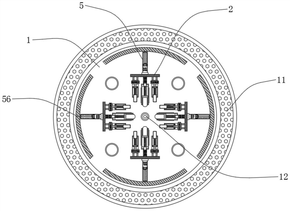
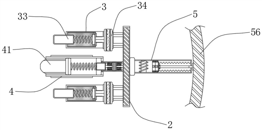
[0027] see Figure 1-6 , a workpiece clamping device for a turntable shot blasting machine, including a turntable 1, a discharge groove 11 is provided on the upper surface of the turntable 1, and a positioning pin 12 is fixedly connected to the center of the top circle of the turntable 1, and the discharge groove 11 is used To discharge the steel shots accumulated on the turntable 1, the positioning pin 12 is used to locate the position of the workpiece. The t...


PUM


Abstract

The invention relates to the technical field of shot blasting machines, and discloses a workpiece clamping device for a rotary table type shot blasting machine. The workpiece clamping device comprisesa rotary table, wherein the top of the rotary table is fixedly connected with a clamp frame; one side of the clamp frame is fixedly connected with an outer clamping base; the inner part of the outerclamping base is filled with electrorheological fluid; the inner part of the outer clamping base is fixedly connected with a flexible part; one end of the flexible part is fixedly connected with an outer ejector rod; the outer ejector rod at the other surface of a workpiece is stressed to extrude the flexible part; the flexible part is used for conducting impact force into a piezoelectric base, sothat an electrolyte plate in the piezoelectric base is deformed; and according to the piezoelectric effect, current is generated on the electrolyte plate, and the current passes through the electrorheological fluid in the outer clamping base, so that the current applies an electric field to the electrorheological fluid, and as a result, the electrorheological fluid is instantly changed into a solid state, the outer ejector rod loses flexibility, the outer ejector rod can stably fix the workpiece, the phenomenon that the workpiece shakes is avoided, and the processing effect of the workpiece is improved.

Description

technical field [0001] The invention relates to the technical field of shot blasting machines, in particular to a workpiece clamping device for a turntable shot blasting machine. Background technique [0002] The turntable shot blasting machine is suitable for casting, forging and heat treatment workshops to clean up attachments such as sand, scale and other attachments on the surface of flat, thin-walled, and small parts that are afraid of collisions. Shot blasting can not only remove the rust on the surface of the workpiece, clean up the rust and dirt on various workpieces, and improve the surface quality of the workpiece; at the same time, it can also improve the internal stress of the workpiece, achieve the purpose of strengthening, and improve the corrosion resistance of the workpiece. Fatigue strength. [0003] In the prior art, in order to fix the workpiece conveniently, fixtures are usually set up to clamp the workpiece. Among them, when processing some workpieces w...

Claims


Application Information

Patent Timeline
IPC IPC(8): B24C9/00B24C3/24
CPCB24C3/24B24C9/00B24C9/006
Inventor 王卫华
Owner 潍坊华星机械有限公司
Features
  • Generate Ideas
  • Intellectual Property
  • Life Sciences
  • Materials
  • Tech Scout
  • Unparalleled Data Quality
  • Higher Quality Content
  • 60% Fewer Hallucinations
Learn More