A kind of injection molding hot runner system

A hot runner and uniform technology, applied in the field of uniform injection molding hot runner system, can solve the problems of difficult maintenance, high cost, and inability to guarantee, and achieve the effect of increasing heat preservation effect, increasing connection strength, and increasing power

Active Publication Date: 2022-07-05
SUZHOU CHENGRUN ELECTRONICS
View PDF0 Cites 0 Cited by
  • Summary
  • Abstract
  • Description
  • Claims
  • Application Information

AI Technical Summary

Problems solved by technology

[0003] Compared with traditional injection molding, hot runner injection molds have the advantages of short molding cycle, saving plastic raw materials, improving product quality, facilitating production automation and expanding the scope of applications. Although compared with traditional injection molding processes, injection molding for hot runner systems The device is more complicated, the cost is higher, and the maintenance is difficult. However, in the production of large products and complex structure products, the hot runner Zusu mold has the advantages that the traditional cold runner mold cannot match
[0004] The injection molding raw material can maintain a relatively stable temperature for a long time in the hot runner system, so that the raw material can maintain a relatively stable and homogeneous shape for a long time before being injected into the mold, which can effectively increase the molding effect of the mold. When the injection process of the hot runner system cannot be uniform, the above characteristics will not be guaranteed. Uneven injection can easily lead to unstable temperature of each part of the raw material, which will lead to the inability of the raw material to be in a homogeneous state, which will easily affect the molding effect of the injection molding product.

Method used


Image

  • A kind of injection molding hot runner system
  • A kind of injection molding hot runner system
  • A kind of injection molding hot runner system

Examples


Embodiment Construction

[0028] The present invention will be further described in detail below with reference to the accompanying drawings and specific embodiments.

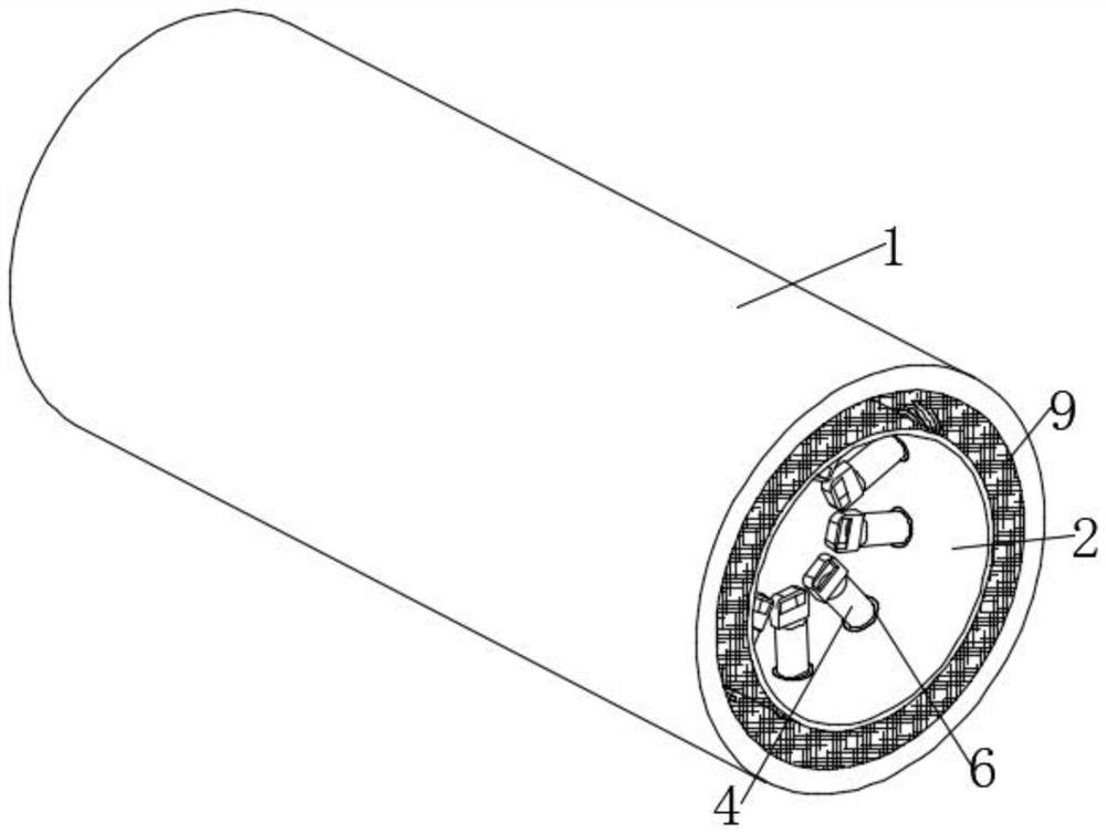
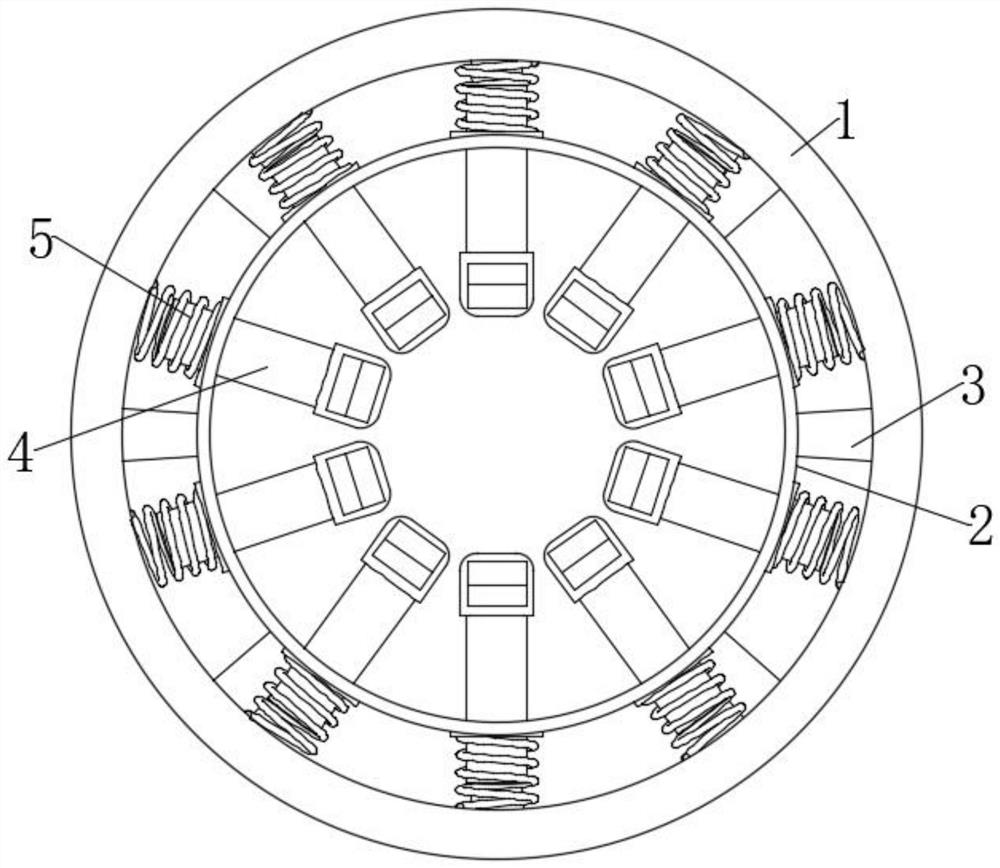
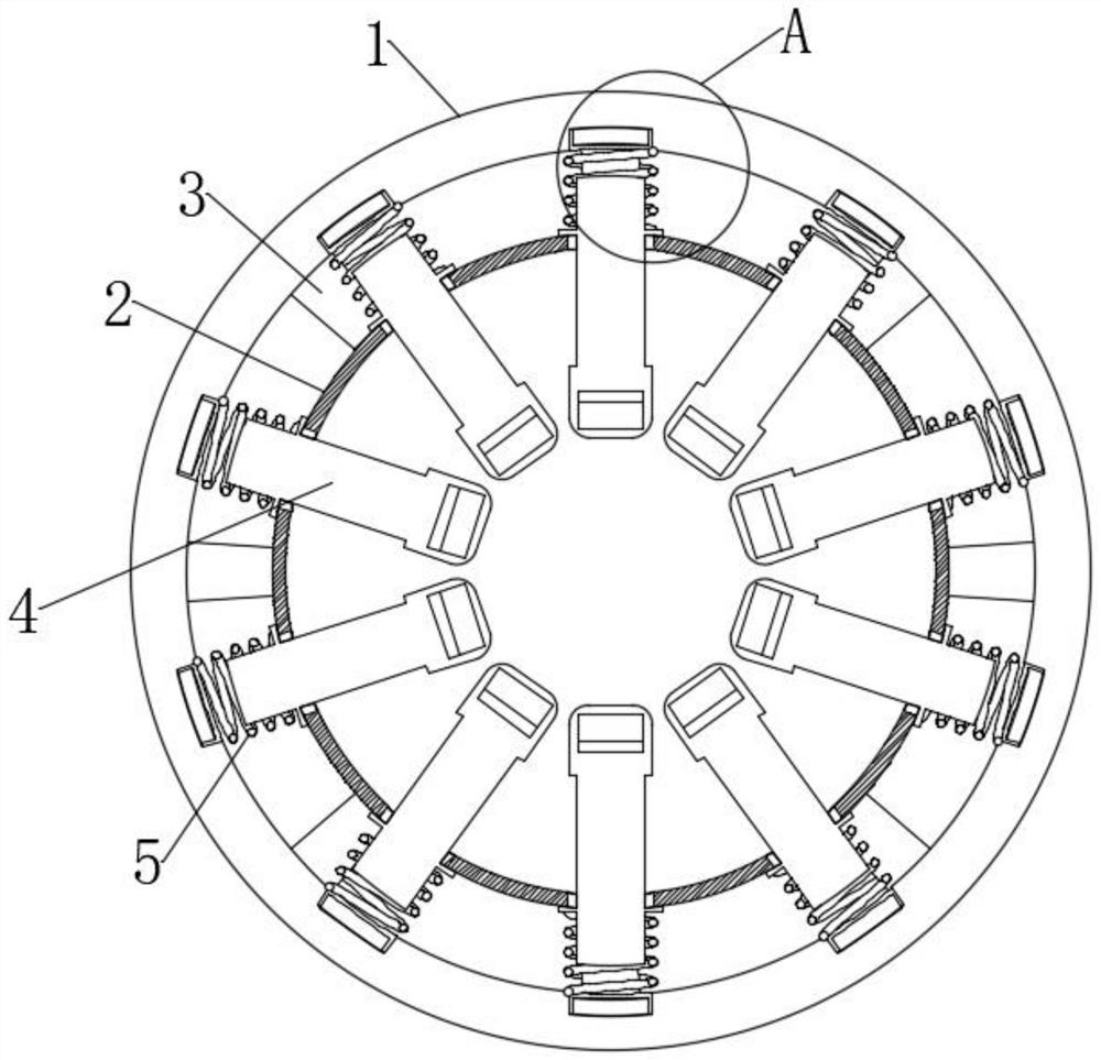
[0029] as attached Figure 1-5 A uniform injection molding hot runner system of the present invention as shown includes a material conveying pipe 2, which is used for conveying injection molding materials, and a sleeve 1 is sleeved on the outer side of the material conveying pipe 2. The sleeve 1 There are multiple groups of connecting columns 3 fixedly connected with the feeding pipe 2, and a plurality of adaptive regulators 4 are arranged in the feeding pipe 2. The adaptive regulator 4 includes a movable rod 401, and one end of the movable rod 401 is fixedly connected with a receiving device. The force block 403, the force block 403 is drilled with a choke groove 404, the cross section of the choke groove 404 gradually decreases with the flow direction of the injection molding material, and the other end of the movable rod 401 penetrat...


PUM


Abstract

The invention relates to a hot runner system for injection molding with uniform material injection. During the use of this solution, when the feeding speed is too slow, on the one hand, the existence of an adaptive regulator will play a role of extrusion buffering for the raw materials, and the raw materials are in After contact with the adaptive regulator, the motion state will change greatly in a short period of time, resulting in the formation of a small range of turbulent flow in the raw material in the fluid state, so that natural deposits cannot be formed inside the raw material. On the other hand, under the action of the raw material fluid , it will push the force block to move in the direction of the inner wall of the conveying pipe, agitate the raw materials in the casing, increase the resistance of the raw materials to flow in the conveying pipe, make it difficult to form natural deposition inside, the raw materials are easy to maintain a homogeneous state, and at the same time can The raw material can be kept warm and heated by the electric heating rod installed inside the movable rod, so that the raw material can maintain a relatively stable and homogeneous shape for a long time before being injected into the mold for molding.

Description

technical field [0001] The invention relates to a hot runner system for injection molding with uniform material injection, in particular to a hot runner system for injection molding with uniform material injection. Background technique [0002] The hot runner is to ensure that the plastic of the runner and gate is kept in a molten state by heating. The hot runner system generally consists of a hot nozzle, a manifold, a temperature control box and accessories. The hot nozzle generally includes two types: open Hot nozzle and needle valve hot nozzle, because the hot nozzle form directly determines the selection of the hot runner system and the manufacture of the mold, so the hot runner system is often divided into an open hot runner system and a needle valve hot runner system accordingly. [0003] Compared with traditional injection molding, hot runner injection molds have the advantages of short molding cycle, saving plastic raw materials, improving product quality, facilitati...

Claims


Application Information

Patent Timeline
Patent Type & Authority Patents(China)
IPC IPC(8): B29C45/27
CPCB29C45/27B29C45/2737B29C2045/2743Y02P70/10
Inventor 周枫岳从新张秀金
Owner SUZHOU CHENGRUN ELECTRONICS
Why Eureka
Try Eureka