Driving motor controller state switching circuit, control method and motor controller

A technology for state switching and driving motors, which can be used in control driving, electric vehicles, electrical devices, etc., and can solve the problems of high power consumption, difficult to support capacitor voltage, reliable maintenance, etc.

Active Publication Date: 2020-12-11
SUZHOU INOSA UNITED POWER SYST CO LTD
View PDF5 Cites 3 Cited by
  • Summary
  • Abstract
  • Description
  • Claims
  • Application Information

AI Technical Summary

Problems solved by technology

At present, the drive motor controller basically adopts switching power supply or linear power supply as the high-voltage power supply supporting the active discharge function. Among them, the switching power supply has high work efficiency but the start-up time is long (millisecond level); although the linear power supply has an extremely short start-up time (microsecond level), but when the supporting capacitor voltage is high, its own power consumption is very large, which will greatly reduce the efficiency of the drive motor controller; and the method of combining the two is too complicated and the technology maturity is low, so it is usually not used
[0003] In the case of "low-voltage power failure after vehicle collision, and the permanent magnet synchronous motor has a high speed", the existing technology relies on the high-voltage power supply to support the active discharge method to realize the discharge function with speed. This method is effective in high-voltage power supply. Under normal circumstances, the discharge function can be completed, but with the progress of active discharge and passive discharge, the voltage of the supporting capacitor will always be lower than the operating voltage threshold of the high-voltage power supply, and finally the drive motor controller will exit the active discharge due to the lack of power supply, and enter Freewheeling by default. (freewheeling) state, since the motor is still running at high speed at this time, the voltage of the supporting capacitor will be rapidly increased by the energy on the motor side and higher than 60V (microsecond level), the existing power supply design scheme cannot guarantee that the voltage of the supporting capacitor will drop When the active discharge function is turned on again before reaching below 60V, it is difficult to reliably reduce the supporting capacitor voltage and maintain the high-voltage safety target of 60V or below 60V

Method used


Image

  • Driving motor controller state switching circuit, control method and motor controller
  • Driving motor controller state switching circuit, control method and motor controller
  • Driving motor controller state switching circuit, control method and motor controller

Examples


Embodiment Construction

[0039] It should be understood that the specific embodiments described here are only used to explain the present invention, not to limit the present invention.

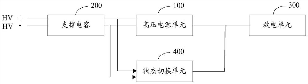
[0040] The embodiment of the present invention provides a drive motor controller state switching circuit, refer to figure 1 , figure 1 It is a structural schematic diagram of the first embodiment of the state switching circuit of the drive motor controller of the present invention.

[0041] The state switching circuit of the drive motor controller includes: a supporting capacitor 200, a high-voltage power supply unit 100, a state switching unit 400, and a discharge unit 300; wherein, the input end of the supporting capacitor 200 is connected to a high-voltage power supply end, and the supporting capacitor 200 The output terminal of the high-voltage power supply unit 100 is connected to the input terminal of the high-voltage power supply unit 100, the output terminal of the high-voltage power supply unit 100 is connec...


PUM


Abstract

The invention relates to the technical field of electric vehicles, in particular to a driving motor controller state switching circuit, a control method and a motor controller. The driving motor controller state switching circuit is characterized in that when a main contactor is disconnected, a state switching unit switches a current working state of a driving motor controller into an ASC state; when the current voltage of a supporting capacitor is smaller than a first preset voltage, the state switching unit switches the current working state of the driving motor controller from the ASC stateinto a Freewheeling state; a high-voltage power supply unit supplies power to a discharge unit and the state switching unit when the main contactor is disconnected and the current voltage of the support capacitor is greater than the first preset voltage; and the discharge unit carries out active discharging. According to the driving motor controller state switching circuit, the active short-circuit state and the follow current state are actively switched according to the current voltage of the support capacitor, so that the discharge unit effectively executes an active discharge function, thevoltage of the support capacitor is always maintained below the preset voltage, and the high-voltage safety target of a whole vehicle is guaranteed.

Description

technical field [0001] The invention relates to the technical field of electric vehicles, in particular to a drive motor controller state switching circuit, a control method and a motor controller. Background technique [0002] In the event of a vehicle crash and low voltage loss, the drive motor controller needs to perform an active discharge function. At present, the drive motor controllers basically use switching power supply or linear power supply as the high-voltage power supply supporting the active discharge function. Among them, the switching power supply has high work efficiency but a long start-up time (millisecond level); although the linear power supply has an extremely short start-up time (microsecond level), but when the supporting capacitor voltage is high, its own power consumption is very large, which will greatly reduce the efficiency of the drive motor controller; and the method of combining the two is too complicated and the technology maturity is low, so...

Claims


Application Information

Patent Timeline
Patent Type & Authority Applications(China)
IPC IPC(8): B60L3/00B60L15/00
CPCB60L3/0007B60L15/00
Inventor 秦秀敬刘畅马梦隐
Owner SUZHOU INOSA UNITED POWER SYST CO LTD
Why Eureka
Try Eureka