Strain calibration device and method for optical fiber sensor

An optical fiber sensor and calibration device technology, which is applied in the direction of using optical devices, measuring devices, instruments, etc., can solve the problems that cannot be fixed, cannot guarantee the uniform sensitivity of sensitive parts, and process errors, and can ensure the accuracy of strain calibration and accurate measurement results. , to ensure the effect of stability

Inactive Publication Date: 2020-12-11
CHINA ELECTRIC POWER RES INST
View PDF7 Cites 3 Cited by
  • Summary
  • Abstract
  • Description
  • Claims
  • Application Information

AI Technical Summary

Problems solved by technology

[0007] The above technology is only applicable to the tension and compression strain detection of metal materials, but the calibration test for strain sensors cannot be realized: it is not conducive to the improvement of industrial mass production efficiency, especially not suitable for optical fiber strain of different specifications and gauge lengths Calibration test of the sensor
[0008] In the prior art, "a number of strain gauges are fixedly arranged on the outer surface of the metal to be tested and connected to the four-terminal resistance box, and the output terminals of the force sensor and the output end of the four-terminal resistance box are respectively connected to the controller", the device The strain value of the metal material is measured by fixing the strain gauge and the four-terminal method resistance box on the metal material, but for the optical fiber strain sensor: this measurement method and measurement device cannot meet the measurement requirements, mainly reflected in: 1 optical fiber strain Sensors (except optical fiber strain gauges) all have casings, and it is impossible to fix resistance strain gauges or four-terminal resistance boxes on the sensitive parts of optical fiber strain sensors; There are many types, and testing equipment that can change the gauge length is required; 3. The processing error of the sensitive parts of the optical fiber strain sensor cannot guarantee the uniform sensitivity of a batch of sensitive parts. Therefore, each optical fiber strain sensor needs strain calibration before leaving the factory and before engineering application. Calibration test equipment requires flexible and convenient operation

Method used


Image

  • Strain calibration device and method for optical fiber sensor
  • Strain calibration device and method for optical fiber sensor
  • Strain calibration device and method for optical fiber sensor

Examples


Embodiment approach

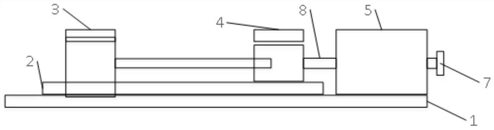
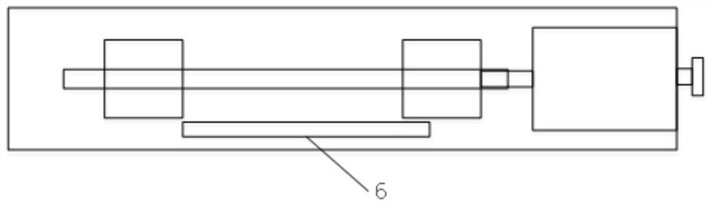
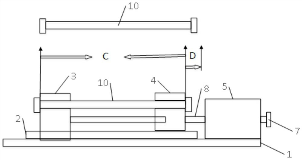
[0035] like figure 1As shown, an embodiment of the present invention provides a strain calibration device for an optical fiber sensor, including: a base 1, a slide rail 2, a fixed block 3, a slide block 4, a transmission seat 5, a power device 7, a displacement transmission device 8 and Measuring device 6; the slide rail 2 and the transmission seat 5 are fixedly installed on the base 1, and one end of the slide rail 2 is provided with a fixed block 3, and the fixed block 3 is installed on the base 1, and the other end is provided with a movable The sliding block 4 moving along the slide rail 2, the optical fiber strain sensor to be tested is clamped between the fixed block 3 and the sliding block 4, the sliding block 4 is connected with the displacement transmission device 8, the power device 7 and the displacement transmission device The device 8 is fixedly connected through the transmission seat 5, and the measuring device 6 is installed on the base 1 for measuring the param...


PUM


Abstract

The invention provides a strain calibration device and method for an optical fiber sensor. The device comprises a base, a sliding rail, a fixed block, a sliding block, a transmission seat, a power device, a displacement transmission device and a measuring device. A to-be-measured optical fiber strain sensor is clamped between the fixed block and the sliding block; the scale distance of the to-be-measured optical fiber strain sensor is measured by using the measuring device; the power device is started, the sliding block moves; when the to-be-measured optical fiber strain sensor deforms, the measuring device is used for measuring and recording the deformation quantity of the to-be-measured optical fiber strain sensor; Calibration parameters are calculated, and calibration is completed. A method for stretching or compressing the to-be-measured optical fiber strain sensor is adopted; the strain value of the to-be-measured optical fiber strain sensor is obtained by dividing the variable quantity of the stretching or compressing by the scale distance. With the method adopted, the strain value can be obtained more visually and accurately.

Description

technical field [0001] The invention relates to the technical field of optical fiber communication, in particular to an optical fiber sensor strain calibration device and method. Background technique [0002] The mechanism of optical fiber sensing is to send the light beam incident from the light source into the sensing front end through the optical fiber, and interact with the external measured parameters in the sensing front end, so that the optical properties of the light in the sensing front end, such as light intensity, wavelength, frequency, etc. , phase, polarization state, etc. change to become a modulated optical signal, and then send it to an optoelectronic device through an optical fiber, and obtain the measured parameters after demodulation. [0003] Optical fiber sensing has many excellent properties, such as: anti-electromagnetic and atomic radiation interference performance, thin diameter, soft, light mechanical properties; insulation, non-inductive electrical...

Claims


Application Information

Patent Timeline
Patent Type & Authority Applications(China)
IPC IPC(8): G01B11/16
CPCG01B11/16
Inventor 闫志学侯继勇韩敏
Owner CHINA ELECTRIC POWER RES INST
Why Eureka
Try Eureka