
Real-time calibration method for PET detector energy peak position drifting

A calibration method and peak position drift technology, applied in the direction of measuring devices, radiation measurement, X / γ / cosmic radiation measurement, etc., can solve the problem of energy peak position drift, gain value increase, SiPM temperature can not be kept at a certain level Temperature and other issues to achieve the effect of improving the signal-to-noise ratio, increasing the transmission rate, and suppressing the proportion of scattering events

Active Publication Date: 2020-12-11
FMI MEDICAL SYST CO LTD
View PDF6 Cites 2 Cited by
  • Summary
  • Abstract
  • Description
  • Claims
  • Application Information

AI Technical Summary

Problems solved by technology

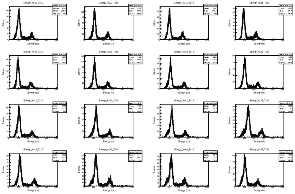
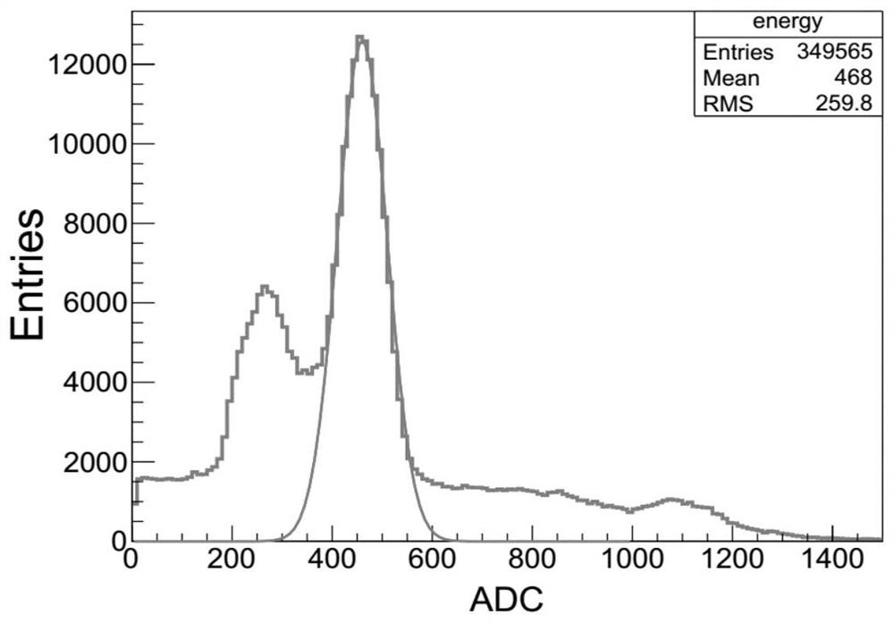
[0004] However, the performance of SiPM is significantly affected by temperature. When the temperature increases, the gain value of SiPM decreases, resulting in a left shift of the energy peak; and when the temperature decreases, the gain value of SiPM increases, resulting in a right shift of the energy peak.
Whether the energy peak shifts to the left or to the right, it will affect the proportion of scattering coincidence events, thereby affecting the signal-to-noise ratio of PET images
[0005] In the prior art, the method for dealing with the drift of the energy peak position with temperature is mainly through an external cooling system, such as: an air cooling system, or a water cooling system, to realize the temperature control of the SiPM, thereby ensuring that the energy peak position does not drift; however, this technology The disadvantage is that because the external cooling system can only ensure that the temperature of the SiPM is controlled within a range, it cannot accurately keep the temperature of the SiPM at a certain temperature.
Therefore, it will also cause a certain drift in the energy peak position due to slight changes in temperature

Method used


Image

  • Real-time calibration method for PET detector energy peak position drifting
  • Real-time calibration method for PET detector energy peak position drifting
  • Real-time calibration method for PET detector energy peak position drifting

Examples


Embodiment Construction

[0030] Below in conjunction with embodiment the present invention is described in further detail.

[0031] This embodiment proposes a real-time calibration method for the drift of the energy peak position of the PET detector. This method is realized based on the host computer directly loading the updated energy calibration table. Offset coefficient peak_per_temp, energy calibration temperature information T0 and energy peak baseline coefficient B, because detector module information, energy peak offset coefficient peak_per_temp and energy calibration temperature information T0 have been determined during the calibration phase (mainly energy peak The determination of the bit offset coefficient, the detector module information and the energy calibration temperature information are determined according to the nature of the equipment), so the update of the energy calibration table in the use stage is mainly for the update of the energy peak baseline coefficient B.

[0032] Such as...


PUM


Abstract

The invention relates to the technical field of medical imaging equipment, in particular to a real-time calibration method for PET detector energy peak position drifting, which is based on an upper computer loading energy calibration table and comprises the following steps of acquiring energy peak position offset coefficients peak_per_temp of all detector modules in a system, and obtaining the temperature difference between the temperatures T of all the detector modules collected at present and the temperature T0 when energy calibration is realized, updating the energy peak position baseline B, and realizing energy peak position drift calibration of all the detector modules of the PET system, so that the energy peak positions of all the detector modules reach the target energy peak positions, and therefore, according to the technical scheme, the scattering event proportion caused by energy peak drifting can be effectively suppressed, so that the transmission rate of effective events iseffectively improved, and the effect of improving the signal-to-noise ratio of the PET image is achieved.

Description

technical field [0001] The invention relates to the technical field of medical imaging equipment, in particular to a real-time calibration method for energy peak position drift of a PET detector. Background technique [0002] Positron Emission Tomography (PET, Positron Emission Tomography) requires the injection of a radioactive tracer before the examination. The tracer can be metabolized by human tissues. Compared with normal tissues, tumors have a higher metabolic level. The principle of PET imaging is: the decay of the tracer produces positrons, and the annihilation of positrons and negative electrons emits two photon pairs with opposite directions and equal energy. Each photon flies at the speed of light. After the detector detects the photon pair, a series of signals processed to reconstruct images with clinical diagnostic significance. [0003] If a pair of gamma photons detected by the detector within a time window come from the same annihilation, the event is called...

Claims


Application Information

Patent Timeline
IPC IPC(8): G01T7/00G01T1/29
CPCG01T7/005G01T1/2985
Inventor 叶宏伟吴国城章波波黄振强
Owner FMI MEDICAL SYST CO LTD
Features
  • Generate Ideas
  • Intellectual Property
  • Life Sciences
  • Materials
  • Tech Scout
  • Unparalleled Data Quality
  • Higher Quality Content
  • 60% Fewer Hallucinations
Learn More