Display panel and display panel manufacturing method

A technology of a display panel and a manufacturing method, which are applied in the directions of instruments, coatings, optics, etc., can solve the problems of excessively large frame of a display device, which is not conducive to the design of narrow frame, and achieve the effect of reducing the frame.

Active Publication Date: 2020-12-11
SHENZHEN CHINA STAR OPTOELECTRONICS SEMICON DISPLAY TECH CO LTD
View PDF13 Cites 0 Cited by
  • Summary
  • Abstract
  • Description
  • Claims
  • Application Information

AI Technical Summary

Problems solved by technology

In the prior art, the data signal transmission line is arranged on the upper end of the display device, and the control signal transmission line is arranged on both sides of the display device. This design method needs to reserve enough non-display space on at least three sides of the display device. area for the setting of the transmission line, which leads to the excessively large frame of the display device, which is not conducive to the realization of a narrow frame design

Method used


Image

  • Display panel and display panel manufacturing method
  • Display panel and display panel manufacturing method
  • Display panel and display panel manufacturing method

Examples


Embodiment Construction

[0037] The following descriptions of the various embodiments refer to the accompanying drawings to illustrate specific embodiments that the present application can be used to implement. The directional terms mentioned in this application, such as [top], [bottom], [front], [back], [left], [right], [inside], [outside], [side], etc., are for reference only The orientation of the attached schema. Therefore, the directional terms used are used to illustrate and understand the application, but not to limit the application. In the figures, structurally similar elements are denoted by the same reference numerals.

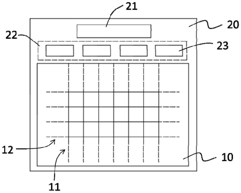
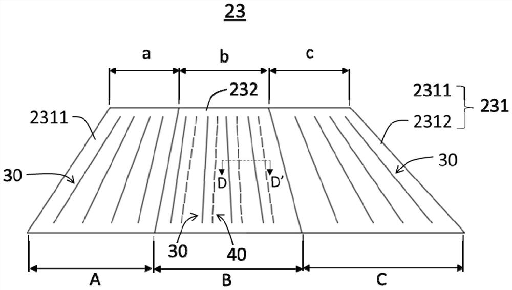
[0038] An embodiment of the present application provides a display panel. The display panel includes a display area and a non-display area located on one side of the display area. The driver chip and the fan-out wiring area are arranged in the non-display area. The fan-out line module is partitioned. In the first wiring area, only the first signal line is used. In the sec...


PUM

PropertyMeasurementUnit
widthaaaaaaaaaa

Abstract

The invention provides a display panel and a display panel manufacturing method, the display panel comprises a display area and a non-display area located at one side of the display area, a driving chip and a fan-out wiring area are arranged in the non-display area, and a fan-out wire module is arranged in the fan-out wiring area. The fan-out wire module comprises a first routing area and a secondrouting area, a first signal wire connected with a data wire is arranged in the first routing area, and a second signal wire connected with a gate wire and the first signal wire connected with the data wire are arranged in the second routing area. According to the display panel, the first signal wires and the second signal wires are jointly arranged in the non-display area on the same side of thedisplay panel, and the fan-out wire modules are partitioned, so that the narrow bezel of the display panel is favorably realized.

Description

technical field [0001] The present application relates to the field of display technology, in particular to a display panel and a method for manufacturing the display panel. Background technique [0002] Liquid Crystal Display (Liquid Crystal Display, LCD) and Organic Light-Emitting Diode (OLED) are currently the two most widely used display technologies. In these two display devices, a thin film transistor (Thin Film Transistor, TFT) is widely used as a display driving element, which is directly related to the display performance of the display device. [0003] The thin film transistor needs to receive control signals and data signals from the outside through gate lines and data lines, and further transmit the data signals to the display unit to control the display function of the display unit. Wherein, the gate line and the data line are connected to the driving chip through transmission wires provided in the non-display area of ​​the display device, so as to receive cont...

Claims


Application Information

Patent Timeline
Patent Type & Authority Applications(China)
IPC IPC(8): G02F1/1345G02F1/1362G02F1/1333
CPCG02F1/13452G02F1/13454G02F1/136286G02F1/1333H01L27/124H10K50/115H10K50/16G02F1/1345G02F1/136295C23C16/06C23C16/56G02F1/133345G02F1/1368H01L27/1259H10K59/131
Inventor 赵迎春
Owner SHENZHEN CHINA STAR OPTOELECTRONICS SEMICON DISPLAY TECH CO LTD
Why Eureka
Try Eureka