Eureka AIR delivers breakthrough ideas for toughest innovation challenges, trusted by R&D personnel around the world.

Wafer chuck for lithography machine

A lithography machine and wafer technology, applied in the field of lithography machines, can solve the problems of complicated operation, difficulty in processing square wafers, inconsistent pattern positions, etc., and achieve the effect of accurate wafer position

Active Publication Date: 2020-12-11
江西芯光微电子有限公司
View PDF4 Cites 1 Cited by
  • Summary
  • Abstract
  • Description
  • Claims
  • Application Information

AI Technical Summary

Problems solved by technology

[0004] However, most of the current lithography machines are used to process circular wafers, which makes it difficult for users to process square wafers
Since the wafer suction cup on the lithography machine is circular, when the user places a square wafer, the geometric center of the square wafer may be deviated from the geometric center of the circular wafer suction cup and placed asymmetrically, causing the square wafer to rise during adjustment. It will move relative to the wafer chuck; it may cause the square wafer to be inclined relative to the mask pattern, causing the pattern transferred to the square wafer on the mask to be inclined relative to the outer frame of the square wafer, which will affect the use; at the same time, it will make Each time the wafer is placed in a different position on the circular wafer chuck, resulting in inconsistent pattern positions for each batch of processed wafers
Although by manipulating the position adjustment axis of the lithography machine, the placement of the cube wafer can be close to the user's needs; however, the adjustment range of these position adjustment functions is relatively small, and the operation is cumbersome, and it is difficult to guarantee the position of each adjustment. The same; so the fundamental way to solve the problem that square wafers are not suitable for placing on circular wafer chucks is to design a wafer chuck with a simple structure and reasonable structure, so that it can not only be suitable for circular wafers, but also meet the needs of users for processing square wafers.

Method used


Image

  • Wafer chuck for lithography machine
  • Wafer chuck for lithography machine
  • Wafer chuck for lithography machine

Examples


Embodiment Construction

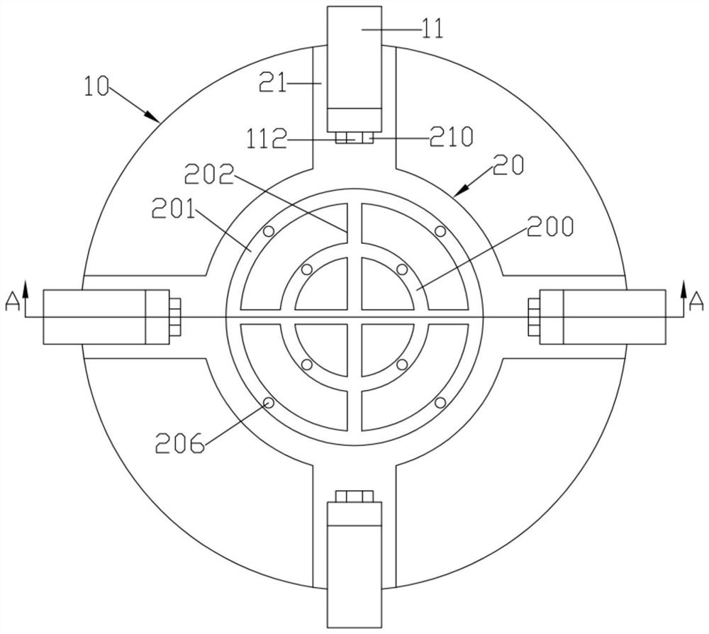
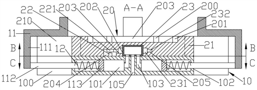
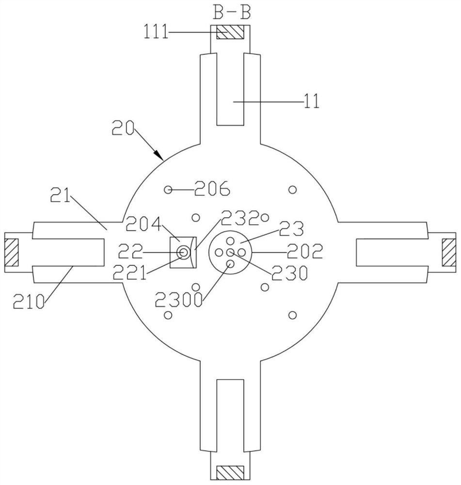
[0019] Such as Figure 1 to Figure 5 Shown, a kind of wafer sucker that is used for lithography machine comprises circular plate-shaped base 10; The upper end surface of base 10 is detachably fixed with circular plate-shaped support platform 20; Both support platform 20 and base 10 The central axis of rotation is set in line; the upper end surface of the support table 20 is formed with a number of coaxial cylindrical groove-shaped adsorption grooves with different diameters; the bottom surface of the adsorption groove is formed with four upper air guide holes 206 that are evenly distributed around the circumference and penetrate up and down; The cylindrical surface of the base 10 is formed with four lower radial moving grooves 100 evenly distributed around the circumference; the center of the lower end surface of the base 10 is formed with an air guide main pipe 105 penetrating up and down; the air guide main pipe 105 is connected to the external suction device; The inside of ...


PUM


Abstract

The invention discloses a wafer chuck for a lithography machine. A cylindrical groove-shaped rotary placement groove is formed in the bottom surface of a supporting table; a cylindrical center switching block is rotationally arranged in the rotary placement groove; four distribution holes which are circumferentially and uniformly distributed are formed in the lower side wall of the central switching block; a central air guide hole communicated with the air guide main pipe is formed in the center of the lower side wall of the central switching block; and L-shaped outer limiting air guide holesare formed in the inner side walls of the inner moving grooves. The upper ends of the outer limiting air guide holes are arranged in a penetrating manner and matched with the distribution holes; fourlower radial air guide pipes which are evenly distributed in the circumferential direction and arranged in the radial direction are formed in the base. The lower radial air guide pipe is positioned between a pair of adjacent inner moving grooves; a plurality of lower air guide holes which are matched with the upper air guide holes and penetrate upwards are formed in the lower radial air guide pipe; and an inner limiting air guide hole which is matched with the distribution hole and penetrates upwards is formed in the inner side end of the lower radial air guide pipe.

Description

technical field [0001] The invention relates to the technical field of photolithography machines, in particular to a wafer chuck used for photolithography machines. Background technique [0002] Photolithography refers to a micro-electro-mechanical processing process that transfers the microstructure pattern on the mask to the wafer coated with photoresist through a series of operation steps. The photolithography process can be used in the manufacture of integrated circuits, microfluidic chips or other micro devices. [0003] The photolithography process is completed on the photolithography machine equipment. In lithography equipment, there are two key modules, namely plate holder and wafer holder. The plate carrier refers to the carrier used to place the lithography mask, which is located in the mask stage subsystem; the carrier table refers to the carrier used to place the wafer, which is located in the workbench subsystem. In the stage module, the device used to place ...

Claims


Application Information

Patent Timeline
IPC IPC(8): G03F7/20
CPCG03F7/707G03F7/70716
Inventor 秦小燕
Owner 江西芯光微电子有限公司
Why Eureka
Eureka Blog
Learn More