

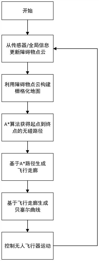
Unmanned aerial vehicle trajectory generation method based on flight corridor and Bezier curve
A Bezier curve, unmanned aerial vehicle technology, applied in the direction of instruments, vehicle position/route/height control, non-electric variable control, etc., can solve the problem of unfavorable robot movement, inability to ensure that the trajectory does not touch obstacles, curved curves, etc. problem, to achieve the effect of being beneficial to the movement of the UAV, the generation of the trajectory, and the increase of the overlapping area.
- Summary
- Abstract
- Description
- Claims
- Application Information
AI Technical Summary
Problems solved by technology
Method used
Image

Examples
Embodiment
[0118] In order to verify the implementation effect of the present invention, a test is carried out in this embodiment in the UAV tracking scene, and the method of the present invention is compared with the Minimum-Snap method.
[0119] Implementation details: Set the path planning end point of the UAV to the real-time position of the dynamically moving target, and refresh the trajectory of the UAV at a frequency of 10Hz to realize tracking.
[0120] The implementation process of the method of the present invention will not be described in detail.
[0121] When the Minimum-Snap method is implemented, due to the large number of original nodes generated by path planning, it is too redundant to be directly used for trajectory generation, which is not good for the smoothness and time efficiency of trajectory generation, so it needs to be simplified. In order to simplify the path and retain the key nodes on the path, this embodiment adopts the Line of Sight algorithm, which is spec...
PUM
 Abstract
Description
Claims
Application Information