
Computer heat dissipation device based on composite heat dissipation technology

A technology of heat dissipation device and computer, applied in computing, supporting machines, mechanical equipment, etc., can solve the problems of poor heat dissipation function, limited heat dissipation effect, and difficulty in heat dissipation of notebook computers, prevent water storage stability, and improve convenience. , The effect of preventing water overflow

Inactive Publication Date: 2020-12-11
ZIBO VOCATIONAL INST
View PDF0 Cites 0 Cited by
  • Summary
  • Abstract
  • Description
  • Claims
  • Application Information

AI Technical Summary

Problems solved by technology

However, due to the compact design of the notebook computer, the heat dissipation function of the notebook computer is very poor, and an external cooling device is usually required for auxiliary heat dissipation.
[0004] At present, although there are many types and quantities of computer heat sinks developed based on technology on the market, their heat dissipation method mainly depends on the direct blowing of fans. This heat calculation method has a very limited heat dissipation effect in summer heat. The temperature rises quickly, it is difficult to play the role of heat dissipation, and the application is very inconvenient

Method used


Image

  • Computer heat dissipation device based on composite heat dissipation technology
  • Computer heat dissipation device based on composite heat dissipation technology
  • Computer heat dissipation device based on composite heat dissipation technology

Examples


Embodiment 1

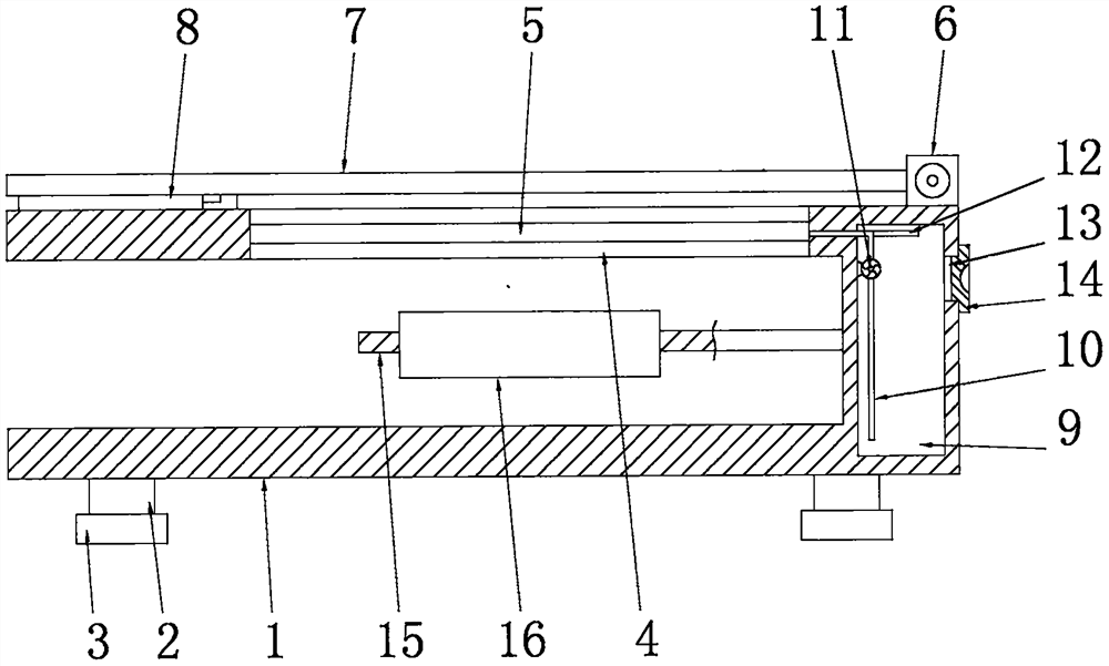
[0034] See Figure 1-2 , a computer heat dissipation device based on composite heat dissipation technology, comprising a frame 1, the frame 1 is a U-shaped structure, the top of the frame 1 is provided with a heat dissipation hole 4, and a cooling component 5 is installed in the heat dissipation hole 4, The top of the frame 1 is provided with a seat plate 7, and one end of the seat plate 7 is hinged on the frame 1 through a hinge seat 6, and the seat plate 7 is evenly provided with some air seepage holes, and the bottom end of the seat plate 7 is close to One side of the movable end is provided with an angle bracket 8, and the side wall of the frame 1 is provided with a water storage chamber 9, and the water inlet end of the cooling assembly 5 is connected to the water inlet pipe 10 through, and the water inlet end of the water inlet pipe 10 Suspended at the bottom of the inner chamber of the water storage chamber 9, a micro water pump 11 is installed on the water inlet pipe 1...

Embodiment 2

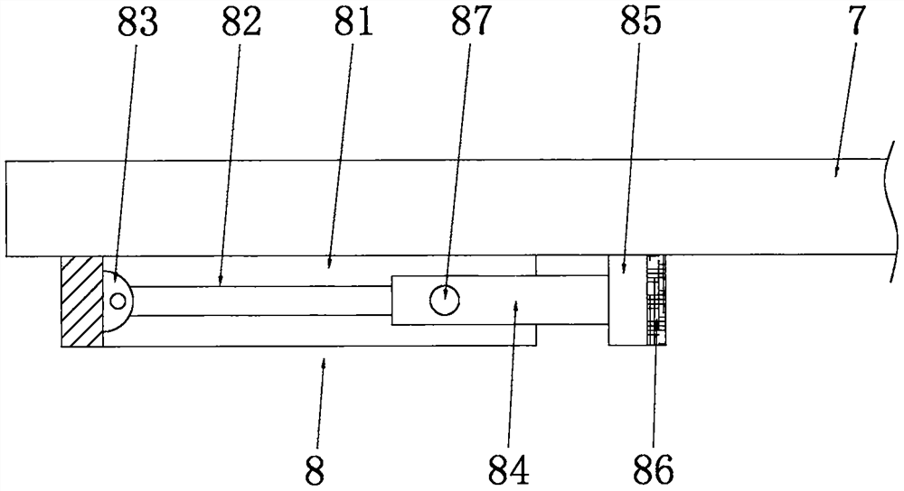
[0040] See image 3 , the difference from Embodiment 1 is that: the corner bracket 8 includes a fixed frame 81, the fixed frame 81 is a U-shaped structure, the fixed frame 81 is fixedly connected to the bottom end of the seat plate 7, and the inner cavity side wall of the fixed frame 81 The telescopic rod 82 is rotated and connected by the twisted shaft 83. The end of the telescopic rod 82 away from the fixed frame 81 is sleeved with a support tube 84. The telescopic rod 82 and the support tube 84 are slidingly connected. The support tube 84 is provided with a The fixed pin 87 matched with the telescopic rod 82, the end of the support tube 84 away from the telescopic rod 82 is fixedly connected to the foot plate 85, the foot plate 85 is provided with an anti-skid pad 86, and the anti-skid pad 86 is made of rubber material. The telescopic rod 82 and the support tube 84 can be unfolded through the twisted shaft 83 and the telescopic rod 82 and the fixed frame 81, and then the se...

Embodiment 3

[0042] See Figure 4-5 The difference from Embodiment 1 is that the cooling assembly 5 includes a bracket 51, the bracket 51 is a ring structure, the bracket 51 is installed in the cooling hole 4, and the bracket 51 is provided with a heat exchange tube 52, the heat exchange pipe 52 is a serpentine pipe structure, the water inlet end of the heat exchange pipe 52 is connected to the water inlet pipe 10, the water outlet end of the heat exchange pipe 52 is connected to the water outlet pipe 12, and the air blown by the blower assembly 16 is directly Enter the inner cavity of the bracket 51 through the heat dissipation hole 4, and the heat exchange tube 52 can be used to exchange heat with the air, thereby reducing the temperature of the air, and the notebook computer can be cooled by direct blowing of low-temperature air to ensure the heat dissipation of the notebook computer. quality.


PUM


Abstract

The invention discloses a computer heat dissipation device based on a composite heat dissipation technology, which comprises a rack, wherein a heat dissipation hole is formed in the top end of the rack; a cooling assembly is arranged in the heat dissipation hole; a seat plate is arranged at the top end of the rack; one end of the seat plate is hinged to the rack through a hinge seat; a plurality of air permeation holes are uniformly formed in the seat plate; an angle support is arranged on the side, close to the movable end, of the bottom end of the seat plate; a water storage cavity is formedin the side wall of the rack; a frame plate is fixedly connected to the side wall of an inner cavity of the rack; and an air blowing assembly is embedded in the frame plate. The air blowing assemblyblows air into the heat dissipation hole, the air directly blows the cooling assembly, meanwhile, a micro water pump extracts water in the water storage cavity in cooperation with a water inlet pipe to inject the water into the cooling assembly, so that heat exchange with the air can be achieved through the cooling assembly, the temperature of the air is reduced, and low-temperature air penetratesthrough the air permeation holes and directly blows a notebook computer on the seat plate. Therefore, the notebook computer can be cooled, and the cooling effect of the notebook computer can be greatly improved.

Description

technical field [0001] The invention relates to the technical field of computer heat dissipation, in particular to a computer heat dissipation device based on composite heat dissipation technology. Background technique [0002] A computer, commonly known as a computer, is a modern electronic computing machine used for high-speed computing. It can perform numerical calculations, logical calculations, and has storage and memory functions. It is a modern intelligent electronic device that can run according to the program and process massive data automatically and at high speed. [0003] A notebook computer, also known as a laptop or a laptop, is a small, portable personal computer, usually weighing 1-3 kilograms. Laptops offer trackpads, or touchpoints, in addition to keyboards, providing better orientation and input capabilities. However, due to the compact design of the notebook computer, the heat dissipation function of the notebook computer is very poor, and an external h...

Claims


Application Information

Patent Timeline
Patent Type & Authority Applications(China)
IPC IPC(8): G06F1/20F16M11/10F16M11/28
CPCF16M11/10F16M11/28G06F1/203
Inventor 赵凯
Owner ZIBO VOCATIONAL INST
Learn More