A new energy dust removal device

A dust removal device and new energy technology, applied in the direction of dust removal, cleaning methods and appliances, chemical instruments and methods, etc., can solve the problems of not being able to achieve a good dust collection effect, unsatisfactory dust removal effect, and difficult to reach dust removal standards , to achieve the effect of improving convenience, improving dust collection efficiency and good adsorption

Active Publication Date: 2021-07-27
无锡谐圣环保设备有限公司
View PDF9 Cites 0 Cited by
  • Summary
  • Abstract
  • Description
  • Claims
  • Application Information

AI Technical Summary

Problems solved by technology

[0002] With the development of social economy and the implementation of the sustainable development strategy of human beings, the development of new energy has become an important research topic for human beings. Among them, solar energy has been widely used as a new energy source. During the processing of the panels on the production line, after cutting and grinding processes, dust will be produced and adhere to the surface of the photovoltaic panel, which needs to be removed by the dust removal device; the dust removal device of the photovoltaic panel in the prior art is mainly directly sucked by the fan. The dust on the photovoltaic panel, the dust removal effect is not ideal, and it is difficult to meet the dust removal standard
[0003] For example, a new energy dedusting device with Chinese patent application number 201921611939.6 is basically described as follows: it includes a conveyor, two vertical plates are fixedly installed on the top of the conveyor, the two vertical plates are arranged symmetrically, and the two vertical plates are connected to each other. The same central axis is installed in rotation on the close side, and the fixed sleeve on the central axis is provided with a roller brush. The new energy dust removal device absorbs the dust through the dust cover, but the adsorption effect on the dust is poor. It is difficult to fully collect the dust, and the ideal dust collection effect cannot be achieved well, which is not conducive to the improvement of dust collection efficiency

Method used


Image

  • A new energy dust removal device
  • A new energy dust removal device
  • A new energy dust removal device

Examples


Embodiment Construction

[0053] The following will clearly and completely describe the technical solutions in the embodiments of the present invention with reference to the accompanying drawings in the embodiments of the present invention. Obviously, the described embodiments are only some, not all, embodiments of the present invention. Based on the embodiments of the present invention, all other embodiments obtained by persons of ordinary skill in the art without making creative efforts belong to the protection scope of the present invention.

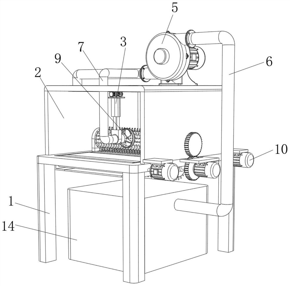
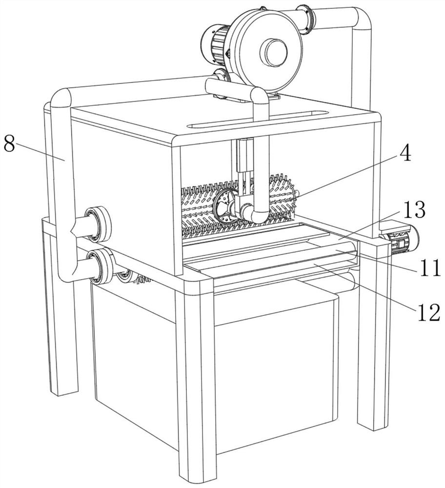
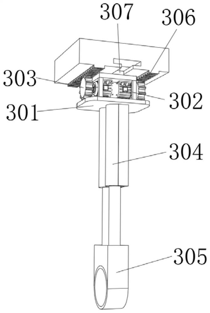
[0054] see Figure 1-4 , the present invention provides a technical solution: a new energy dust removal device, including a support frame 1, the upper surface of the support frame 1 is fixedly connected with a stabilizing frame 2, and the rear side of the inner top side wall of the stabilizing frame 2 is provided with a sliding dust suction device 3. The sliding dust collection device 3 drives the dust collection cover 9 to move left and right for a more compr...


PUM


Abstract

The invention relates to the technical field of dust removal devices, and discloses a new energy dust removal device, which includes a support frame, the upper surface of the support frame is fixedly connected with a stabilizer, and the rear side of the inner top side wall of the stabilizer is provided with a rotating suction Dust device, the top of the support frame is provided with a sliding dust suction device, the left side of the upper surface of the stable frame is fixedly connected with a vacuum cleaner, and the output end of the vacuum cleaner is connected with an output pipe. The new energy dust removal device, through the rotation of the dust collection device and the vacuum cleaner and the dust collection hood, performs multi-level treatment on the dust generated during cleaning, which has better dust removal effect, can better remove the dust on the photovoltaic panel, and is more efficient The dust can be fully collected to achieve a more ideal dust collection effect, which greatly improves the dust suction efficiency, avoids the dust from flying around and affects the surrounding environment, and further improves the convenience of use.

Description

technical field [0001] The invention relates to the technical field of dust removal devices, in particular to a new energy dust removal device. Background technique [0002] With the development of social economy and the implementation of the sustainable development strategy of human beings, the development of new energy has become an important research topic for human beings. Among them, solar energy has been widely used as a new energy source. During the processing of the panels on the production line, after cutting and grinding processes, dust will be produced and adhere to the surface of the photovoltaic panel, which needs to be removed by the dust removal device; the dust removal device of the photovoltaic panel in the prior art is mainly directly sucked by the fan. For the dust on the photovoltaic panels, the dust removal effect is not ideal, and it is difficult to meet the dust removal standard. [0003] For example, a new energy dedusting device with Chinese patent ...

Claims


Application Information

Patent Timeline
Patent Type & Authority Patents(China)
IPC IPC(8): B08B1/02B08B1/00B08B15/04B08B15/02B08B13/00
CPCB08B1/002B08B1/02B08B13/00B08B15/02B08B15/04
Inventor 刘延改
Owner 无锡谐圣环保设备有限公司
Why Eureka
Try Eureka