Accurately-adjustable stopper

A stopper and precise technology, which is applied in the direction of processing discharged materials, feeding devices, positioning devices, etc., can solve the problems of inaccurate positioning and space occupied by stoppers, so as to improve work efficiency, make manufacturing simple and convenient, reduce Small footprint effect

Pending Publication Date: 2020-12-15
东实(武汉)实业有限公司
View PDF0 Cites 0 Cited by
  • Summary
  • Abstract
  • Description
  • Claims
  • Application Information

AI Technical Summary

Problems solved by technology

[0004] The object of the present invention is to propose a stopper that can be precisely adjusted to solve the problem that the single setting of the stopper in the prior art cannot be used universally and takes up a lot of space, and the position of the existing stopper is engraved or marked, resulting in The problem of inaccurate positioning

Method used


Image

  • Accurately-adjustable stopper
  • Accurately-adjustable stopper
  • Accurately-adjustable stopper

Examples


Embodiment Construction

[0026] In order to make the object, technical solution and advantages of the present invention clearer, the present invention will be further described in detail below in conjunction with the accompanying drawings and embodiments. It should be understood that the specific embodiments described here are only used to explain the present invention, not to limit the present invention.

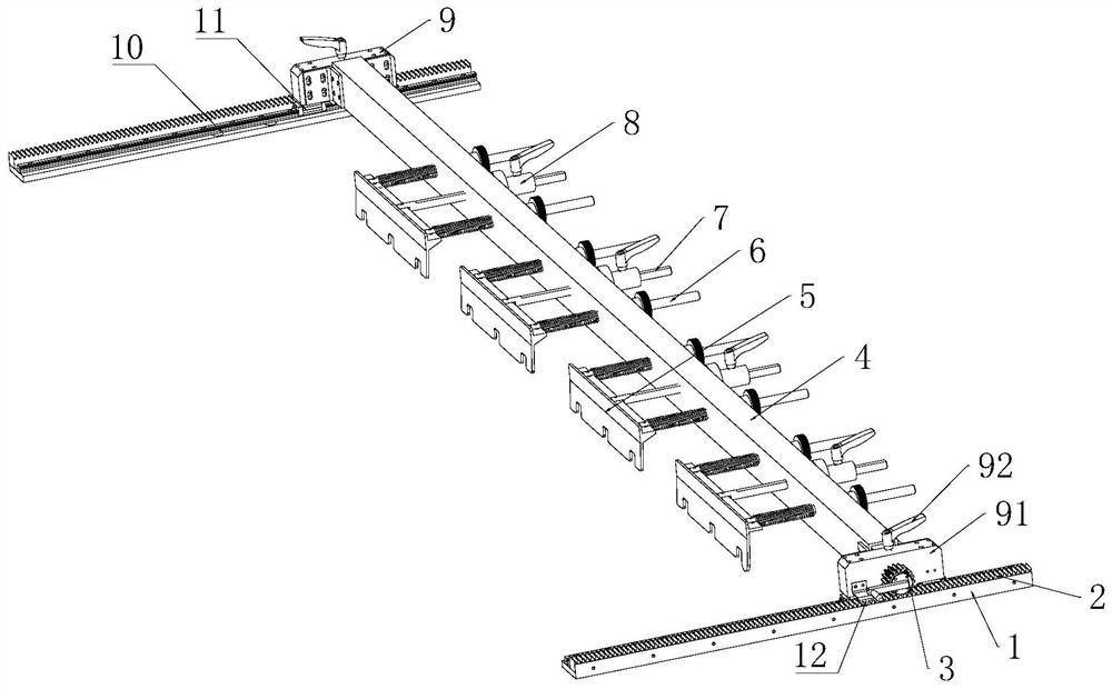
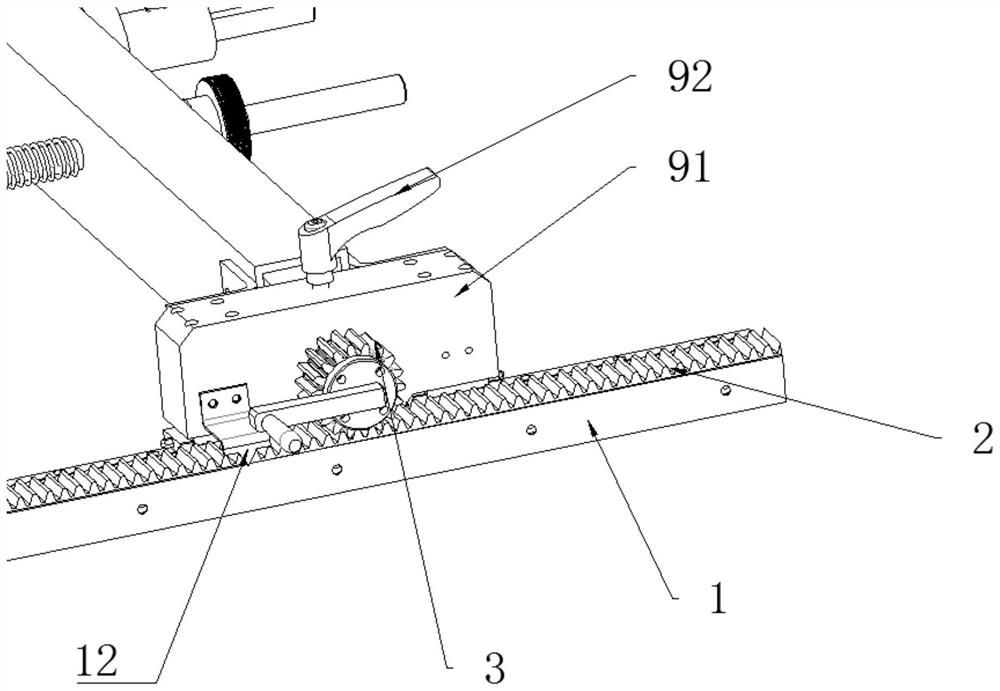
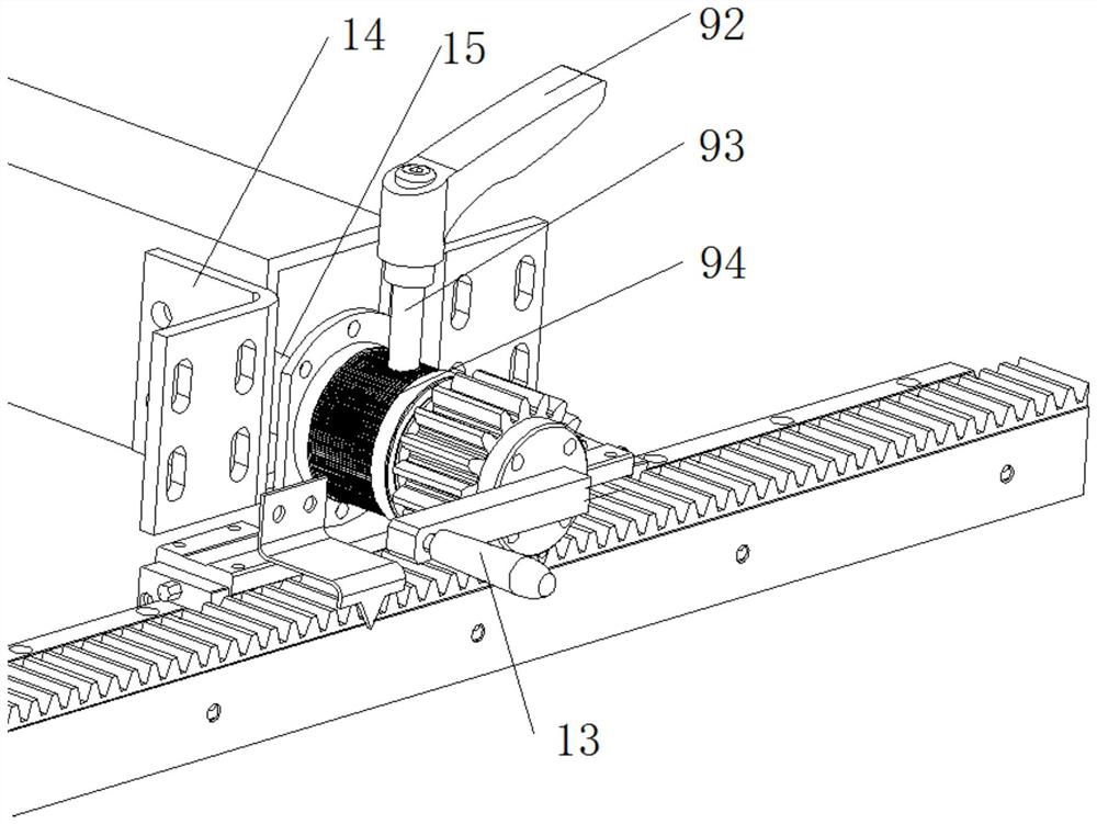
[0027] like Figure 1 to Figure 4 As shown, this embodiment provides a precisely adjustable stopper, including a pair of parallel rack bases 1 arranged at intervals, and a rack 2 is fixedly installed on the two rack bases 1, wherein A scale is provided on one side of at least one of the racks 2 or the rack base 1 . In use, the two rack bases 1 are fixed on both sides of the heating furnace discharge platform.

[0028] The stopper also includes two symmetrically arranged pinion gears 3 meshing with the two racks 2 respectively, a main rod bracket 4 connecting the two pinion gears 3 and at least on...


PUM


Abstract

The invention discloses an accurately-adjustable stopper. The accurately-adjustable stopper comprises a pair of parallel rack seats arranged at an interval, two pinions symmetrically arranged and separately meshed with two racks, a main rod support and at least one material blocking device, the two racks are fixedly mounted on the two rack seats separately, and scales are arranged on one side of one rack or one side of the rack seat; the two ends of the main rod support are rotationally connected with the two pinions through rotating shafts separately, and a pointer for indicating the scales is fixedly installed on one side of the main rod support; and each material blocking device comprises a material blocking plate, at least one guide rod and a scaleplate scale shaft, the guide rods andthe scaleplate scale shafts are fixedly installed on one sides of the material blocking plates, and the scaleplate scale shafts and the guide rods penetrate through the main rod support and extend towards the other side of the main rod support. According to the accurately-adjustable stopper, high-precision positioning can be achieved, and meanwhile the working efficiency can further be improved.

Description

technical field [0001] The present invention relates to the technical field of hot stamping equipment, and more specifically, to a precisely adjustable stopper. Background technique [0002] In the production process of thermoforming parts, usually in order to improve the efficiency of the parts, a multi-cavity parallel mold will be developed and used, that is, different parts are placed in the same set of molds to make multi-cavity molds, and each punch can produce multiple Components. But usually the size of the parts in this one-mold multi-cavity mold is different. In order to ensure that the stamping center is located in the center of the press machine as much as possible, the layout of the parts in the mold will have a front-to-back drop. In order to ensure that the blanks can be accurately put into the mold after being picked up by the mechanical arm on the centering platform, the distribution of the blanks on the centering platform of the heating furnace must be cons...

Claims


Application Information

Patent Timeline
IPC IPC(8): B21D22/02B21D43/00B21C51/00F27D15/00
CPCB21C51/00B21D22/022B21D43/003F27D15/00
Inventor 余冬晴雷涛贺东方刘鹏尤宝卿刘祥罗帆
Owner 东实(武汉)实业有限公司
Why Eureka
Try Eureka