
Drilling equipment for PCB production

A technology of PCB board and drilling equipment, applied in metal processing and other directions, can solve the problems of operator's personal safety threat, affecting processing efficiency, poor processing continuity, etc., to save waiting time, shorten processing cycle, and ensure the effect of yield rate

Inactive Publication Date: 2020-12-15
天津玖源自动化设备有限公司
View PDF9 Cites 1 Cited by
  • Summary
  • Abstract
  • Description
  • Claims
  • Application Information

AI Technical Summary

Problems solved by technology

Patent No. 201821509702.2 discloses a drilling device based on PCB boards, which can drill holes in PCB boards, but it has the following defects: (1) It is easy to generate a lot of debris when drilling, and debris With the high-speed rotation of the drill bit, it splashes around the machine and is difficult to clean; (2) When loading materials, the PCB board needs to be manually placed on the upper end of the drilling platform. Since the drill bit is facing the drilling platform, when the operator misuses, It will cause the drill bit to go down directly, which poses a certain threat to the personal safety of the operator; (3) After the drilling process, the operator needs to manually unload the material, which affects the processing efficiency; (4) The next loading needs to wait for the previous unloading It can only be carried out after the material is completed, and there is a certain waiting time in the process, resulting in poor continuity of processing

Method used


Image

  • Drilling equipment for PCB production
  • Drilling equipment for PCB production

Examples


Embodiment Construction

[0019] The content of the present invention will be described below in conjunction with specific embodiments.

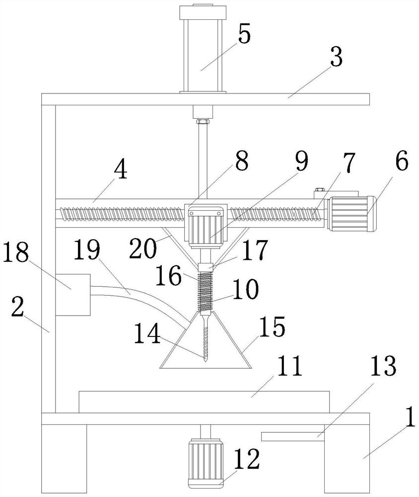
[0020] refer to figure 1 , a PCB board drilling device proposed by the present invention includes a base 1 and a bracket connected to the base 1, a rotary feeding unit is installed on the base 1, and a drilling unit is installed on the bracket. The drilling unit includes a drill bit 10 , and the rotary feeding unit is used to transport the PCB board directly under the drill bit 10 .

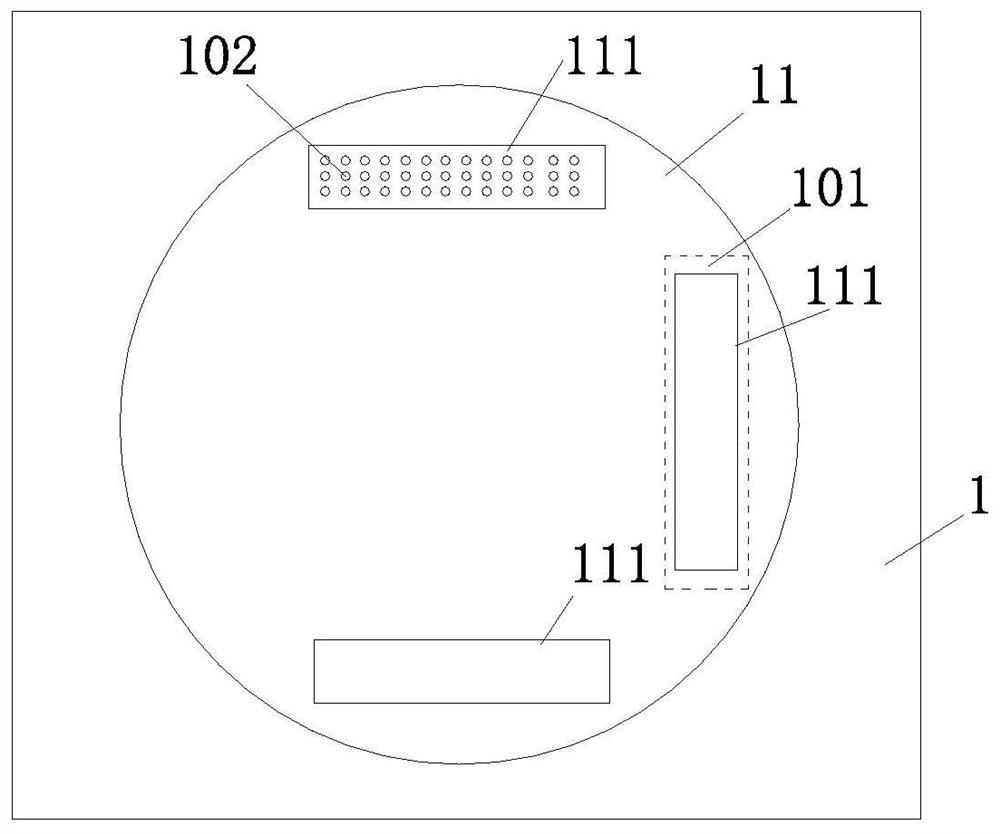
[0021] The rotary material unit includes a rotary table 11 rotatably connected to the base 1, the rotary table 11 is supported by the base 1, a shaft hole is opened through the base 1, and the bottom of the base 1 is installed with The third motor 12 , the output shaft of the third motor 12 is fixedly connected to the turntable 11 through the shaft hole, and the output shaft of the third motor 12 is arranged coaxially with the turntable 11 . refer to figure 2 At least three limiting...


PUM


Abstract

The invention relates to drilling equipment for PCB (printed circuit board) production. The drilling equipment comprises a base and a support connected with the base, and is characterized in that a drilling unit is installed on the support, and a rotary feeding unit for conveying a PCB to the lower part of the drilling unit is installed on the base; the drilling unit comprises a lifting base, thelifting base is driven by an air cylinder to move up and down, a sliding block is slidably connected with the lifting base, a first motor is installed on the sliding block, the periphery of an outputshaft of the first motor is sleeved with a sleeve, and the sleeve is rotatably connected with the output shaft of the first motor and fixedly connected with the lifting base through a pull rod; an output shaft of the first motor is in driving connection with a drill rod, the periphery of the drill rod is sleeved with a pressing cover, and the pressing cover is connected with the sleeve through a spring; a drill bit is installed on the lower portion of the drill rod and located in the pressing cover in a natural state; the pressing cover is provided with an air opening, and the air opening is in communication with an exhaust fan through an exhaust pipe. The drilling equipment has the advantages that safety is high, the machining period is short, the yield is high, and drilling cuttings cannot be splashed everywhere in the machining process.

Description

technical field [0001] The invention relates to the field of PCB board processing, in particular to a drilling device for PCB board production. Background technique [0002] PCB circuit board, also known as printed circuit board, is the provider of electrical connection for electronic components. In the process of production and processing, the PCB board often needs to be punched to facilitate the later assembly and fixing of the PCB board. Patent No. 201821509702.2 discloses a drilling device based on PCB boards, which can drill holes in PCB boards, but it has the following defects: (1) It is easy to generate a lot of debris when drilling, and debris With the high-speed rotation of the drill bit, it splashes around the machine and is difficult to clean; (2) When loading materials, the PCB board needs to be manually placed on the upper end of the drilling platform. Since the drill bit is facing the drilling platform, when the operator misuses, It will cause the drill bit t...

Claims


Application Information

Patent Timeline
Patent Type & Authority Applications(China)
IPC IPC(8): B26F1/16B26D7/02B26D7/18B26D7/22B26D7/32
CPCB26D7/025B26D7/1863B26D7/22B26D7/32B26D2007/322B26F1/16
Inventor 刘广佳杨蕾王玉静
Owner 天津玖源自动化设备有限公司
Learn More