Large-span prestressed concrete shell plate with cylindrical inner wall and pouring device thereof

A large-span, pre-stressed technology, applied in unloading devices, buildings, building structures, etc., can solve the problems of uneven thickness of concrete inner wall, unable to meet the requirements of component accuracy, large diameter of roller shaft, etc., to reduce mold investment, High stiffness and good integrity

Active Publication Date: 2020-12-15
常州市武进建筑设计院有限公司
View PDF9 Cites 0 Cited by
  • Summary
  • Abstract
  • Description
  • Claims
  • Application Information

AI Technical Summary

Problems solved by technology

However, if the suspension roller method uses a large-span cylindrical shell plate, the calculation shows that when the span is greater than 12m, the diameter of the roller shaft is already very large, and its bending deformation will cause uneven thickness of the inner wall of the concrete, which cannot meet the precision requirements of the component

Method used


Image

  • Large-span prestressed concrete shell plate with cylindrical inner wall and pouring device thereof
  • Large-span prestressed concrete shell plate with cylindrical inner wall and pouring device thereof
  • Large-span prestressed concrete shell plate with cylindrical inner wall and pouring device thereof

Examples


Embodiment 1

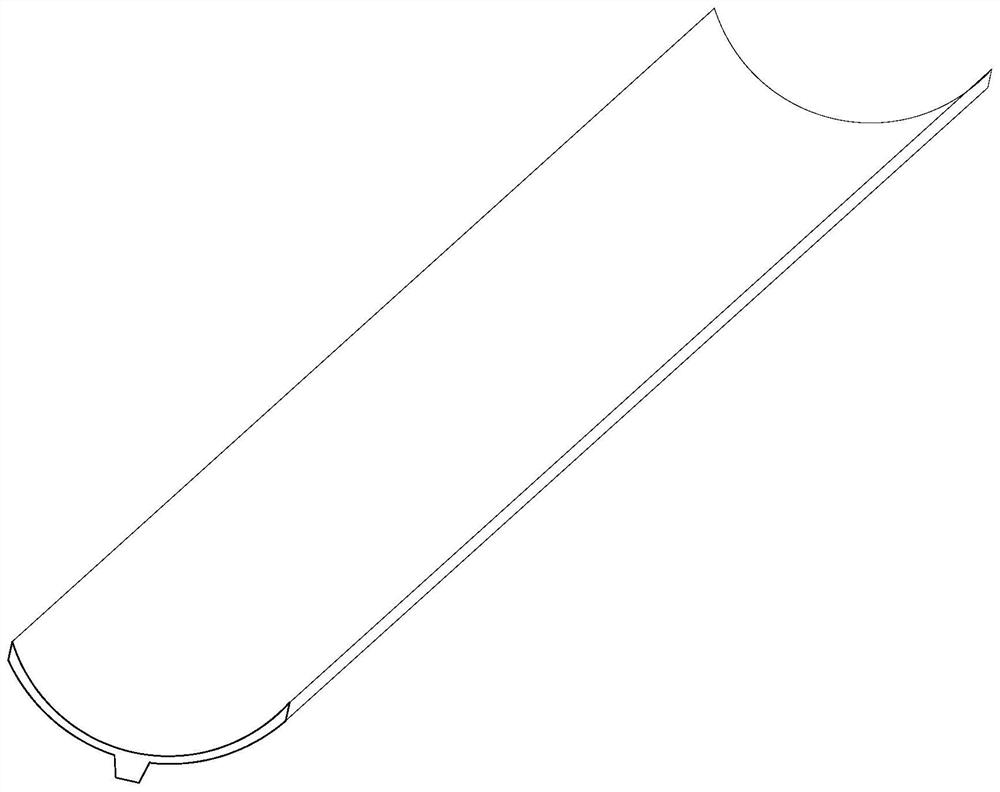
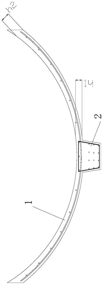
[0042] Such as Figure 1~2 The inner wall shown is a cylindrical long-span prestressed concrete shell plate, with a curved flange plate 1, and a main rib 2 is provided at the center of the outer peripheral surface of the flange plate 1, and the main rib 2 is along the length direction of the flange plate 1 Setting, the flange plate 1 is a 1 / 3 circular arc plate; the cross section of the main rib 2 is trapezoidal, and the large end of the main rib 2 is connected with the flange plate 1; when the span of the flange plate 1 is <21m, the flange plate 1 Thickness h2 of end portion = central thickness h1 of flange plate 1 .

[0043] The inner steel strands 16 are concentratedly arranged in the main rib 2, and the inner steel strands 16 are under tension and the flange plate 1 is under compression, resisting the bending moment of the concrete shell.

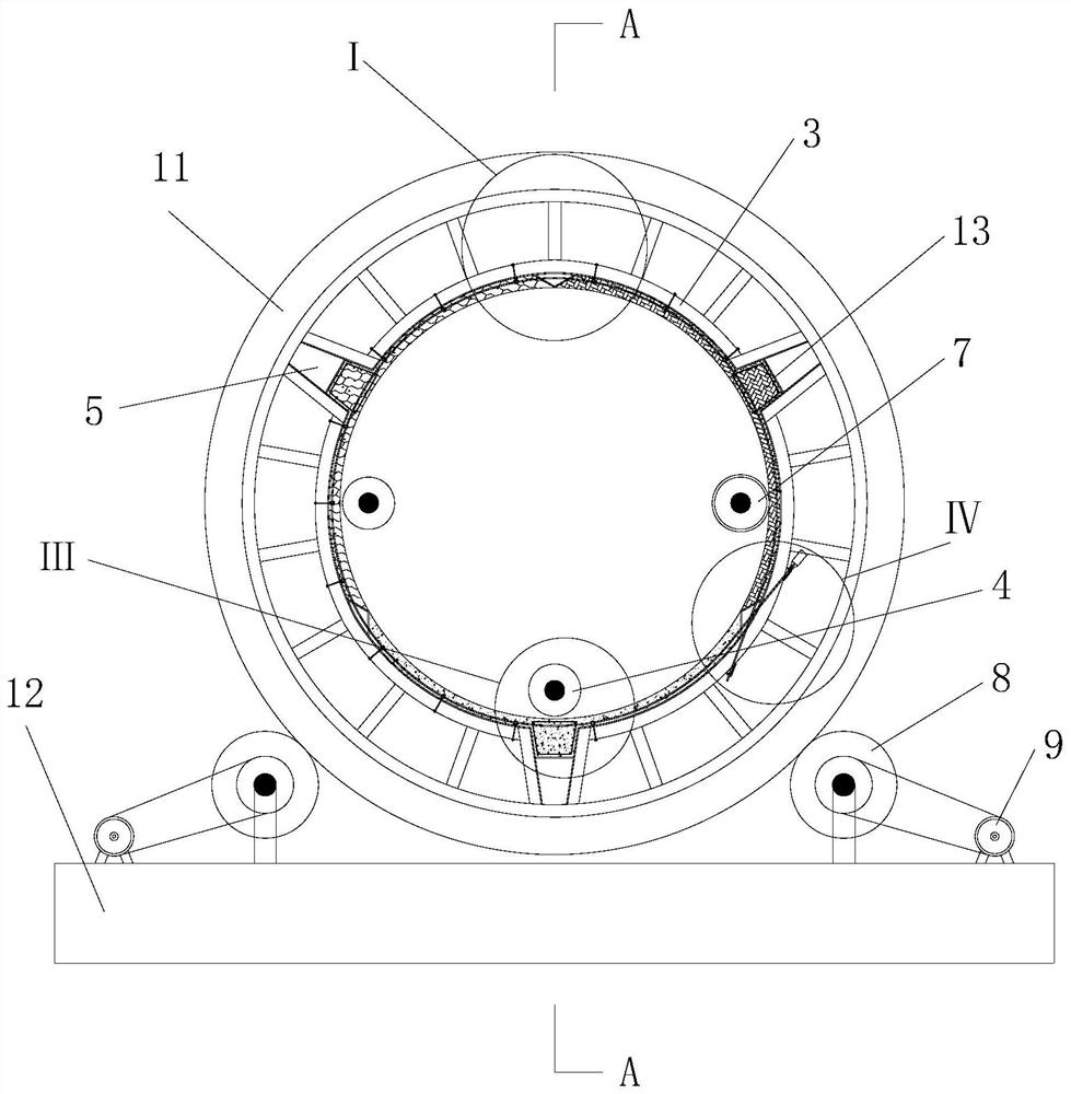
[0044] Such as Figure 3-5 , Figures 9 to 11As shown, a pouring device for pouring the above-mentioned large-span prestressed conc...

Embodiment 2

[0056] The difference from Embodiment 1 is that when the span of the flange plate 1 is ≥ 21 m, the thickness h2 of the end of the flange plate 1 > the thickness h1 of the center of the flange plate 1 can prevent the upper end of the flange plate 1 from being unstable.

[0057] The side formwork unit in the pouring device is a square pipe with variable cross-section bent into an arc-shaped pipe, and the thickness h3 of the side formwork unit is consistent with the thickness direction of the flange plate.


PUM


Abstract

The invention discloses a large-span prestressed concrete shell plate with a cylindrical inner wall and a pouring device thereof. The large-span prestressed concrete shell plate with the cylindrical inner wall is provided with an arc-shaped flange plate; a main rib is arranged in the central position of the peripheral surface of the flange plate and arranged in the length direction of the flange plate; and the thickness h2 of the end of the flange plate is larger than or equal to the thickness h1 of the center of the flange plate. The pouring device is provided with a roller and a feeding device; grooves and a separation steel plate are arranged on the inner wall of the roller; the separation steel plate is located between the two grooves; ribbed beam bottom formworks are arranged in the grooves; a driven shaft is arranged in an inner cavity of the roller; the feeding device comprises a spiral conveying shaft; the spiral conveying shaft is located at the bottom of the roller; and the driven shaft is located above the spiral conveying shaft; and a driving device for driving the roller to rotate is arranged on the outer wall of the roller. The poured large-span prestressed concrete shell plate with the cylindrical inner wall has the advantages that the stress is reasonable, the structure is simple, the manufacturing is convenient, the durability is high and the economical efficiency is good; and the pouring device has the advantages that the mechanization degree is high, and the production efficiency of the pouring device is 10 times or above that of traditional production.

Description

technical field [0001] The invention relates to the technical field of concrete shell plates and pouring, in particular to a large-span prestressed concrete shell plate with a cylindrical inner wall and a pouring device thereof. Background technique [0002] Traditional long-span concrete roofs generally use prefabricated prestressed concrete roof slabs with good economy, especially prefabricated double T slabs, prefabricated saddle slabs, and prefabricated goose-shaped slabs that combine slabs and beams. What they have in common is that ① using prefabricated components, factory production, assembly construction, easy quality control, fast construction speed, energy saving and water saving, in line with the national prefabricated building policy orientation. ② High-strength concrete and high-strength steel bars are used to save materials. ③ Plate and girder are integrated, easy to manufacture, less components, fast transportation and hoisting, good longitudinal rigidity, an...

Claims


Application Information

Patent Timeline
IPC IPC(8): E04D3/26E04B1/342B28B1/20B28B11/24B28B13/06
CPCB28B1/20B28B11/245B28B13/06E04B1/342E04D3/26
Inventor 汤建峰王晓春
Owner 常州市武进建筑设计院有限公司
Why Eureka
Try Eureka