A walking robot with functions of anchor, support and protection
What is Al technical title?
Al technical title is built by PatSnap Al team. It summarizes the technical point description of the patent document.
A step-by-step, robotic technology, used in temporary shields, installation of anchor rods, shaft equipment, etc., can solve the problems of travel speed restriction, equipment travel resistance, and heavy support planes, so as to increase the contact area and stabilize the operation process. , the effect of flexible turning angle
Active Publication Date: 2021-07-30
ANHUI UNIV OF SCI & TECH
View PDF9 Cites 1 Cited by
Summary
Abstract
Description
Claims
Application Information
AI Technical Summary
This helps you quickly interpret patents by identifying the three key elements:
Problems solved by technology
Method used
Benefits of technology
Problems solved by technology
The former has a small contact area with the ground of the roadway and a large specific pressure to the ground, which may easily cause the subsidence of the hydraulic outriggers, and the overall safety of the support system is poor
The latter uses a large plane connecting plate as the support plane. Although the problem of equipment subsidence is solved, the lifting height of the support plane is limited due to the bulky support plane. restrict
[0006] 2) The maneuverability of the equipment is poor, and the turning is not flexible
Obviously, this turning method limits the flexibility of the whole set of equipment, and it is difficult to use it in the roadway with a small turning radius.
[0008] 3) The anchoring and laying process requires manual operation, and the degree of automation is not high
The speed of workers laying anchor nets and moving anchor rods is relatively slow, and the anchor support equipment needs to be stopped and waited, which affects the speed of anchoring and tunneling to a certain extent
Method used
Image
Click on the blue label to locate the original text in one second.
Reading with bidirectional positioning of images and text.
Examples
Embodiment Construction
[0057] In order to make the technical means, creative characteristics of the present invention, it is readily described in connection with the accompanying drawings and specific embodiments, in connection with the accompanying drawings and specific embodiments. It should be understood that the specific embodiments described herein are merely intended to illustrate the invention and are not intended to limit the invention.
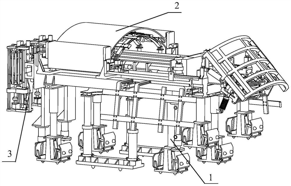
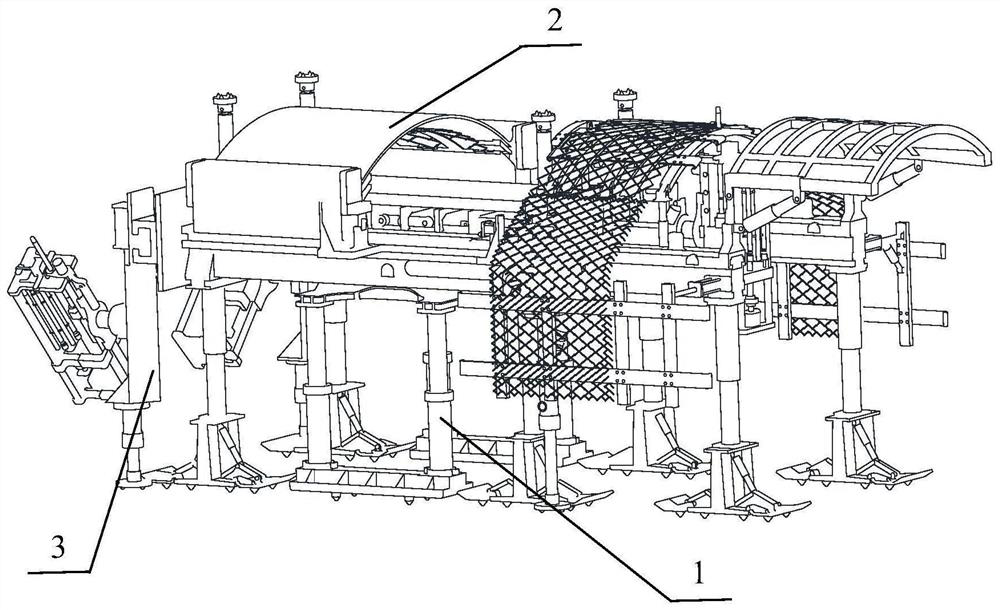
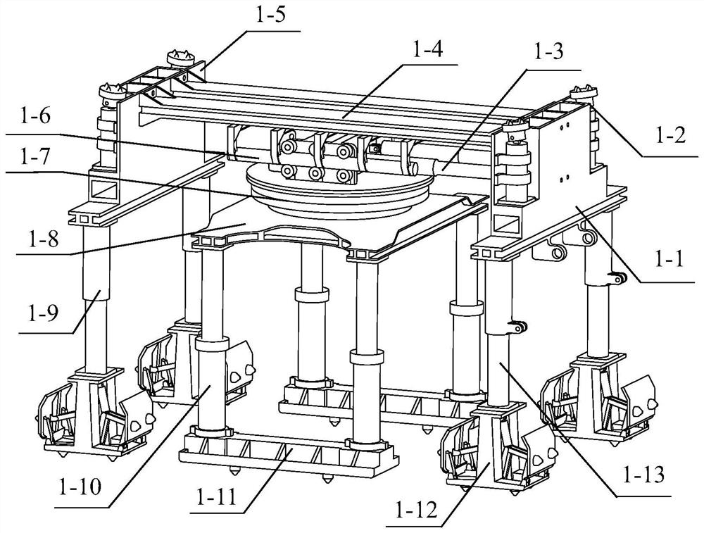
[0058] See figure 1 , A macho robot with anchor, support, protective function, includes walking system 1, wound system 2, and anchoring system 3; the walking system 1 is mounted below the networked system 2; The system 2 is mounted on the front frame 1-1 of the traveling system 1 by a bolt connection; the anchoring system 3 is mounted in the walking through the pin connection and the bolt connection. The front rack 1-1 of the system 1, the rear rack 1-5. A macho robot with anchor, support, protective function, characterized in that the walking system 1 of the d...
PUM
Abstract
The invention discloses a walking robot with the functions of anchoring, supporting and protecting, which comprises three parts: a walking system, a net laying system and an anchoring system. The walking system is installed under the net-laying system to provide support for the whole machine equipment and facilitate the movement of the whole machine in the roadway; the net-laying system is installed on the outer sides of the front and rear racks of the walking system for The whole machine equipment provides support, net storage and net laying functions; the anchoring system is respectively installed on the front and rear racks of the walking system through pin connection and bolt connection, and provides anchoring functions for the whole machine equipment. Further, the present invention is small in size and compact in structure, and has the functions of net storage and laying and multi-bolt cooperative operation, and the equipment support system adopts a multi-stage composite structure to ensure that the whole machine travels and the operation process is stable; a hydraulic rotary mechanism is used as a The turning drive parts of the whole machine make the turning of the equipment more flexible and the maneuverability better.
Description
Technical field [0001] The present invention relates to the field of smothered mechanical and electrical equipment, and in particular to a macho robot with anchor, support, protective function, is an anchor, support, and intelligent equipment range. Background technique [0002] With the continuous development of intelligence, information technology, the coal mine has set off a new wave of innovation, "unmanned / less people, intelligent efficient, green safety" has become the most urgent needs of current coal mining. At present, in the field of electromechanical equipment in the cover, the development of the equipment is more rapid, the product has many types, high automation level, and some products can achieve remote operation and intelligent operation. However, with the anchor, support, support, support, and low function, low operation efficiency, and severely restrictive speed. [0003] Traditional anchor, support, and care ready for manual transport to the designated work s...
Claims
Application Information
Patent Timeline
Application Date:The date an application was filed.
Publication Date:The date a patent or application was officially published.
First Publication Date:The earliest publication date of a patent with the same application number.
Issue Date:Publication date of the patent grant document.
PCT Entry Date:The Entry date of PCT National Phase.
Estimated Expiry Date:The statutory expiry date of a patent right according to the Patent Law, and it is the longest term of protection that the patent right can achieve without the termination of the patent right due to other reasons(Term extension factor has been taken into account ).
Invalid Date:Actual expiry date is based on effective date or publication date of legal transaction data of invalid patent.