Tissue specimen collection mechanism and sample tube

A tissue sample and collection mechanism technology, which is applied in the fields of inoculation ovulation diagnosis, medical science, surgery, etc., can solve the problems of low efficiency and difficult operation of manual separation of tissue samples, and achieve the effect of high collection efficiency and convenient operation

Pending Publication Date: 2020-12-18
宁波之凌智能科技有限责任公司
View PDF0 Cites 2 Cited by
  • Summary
  • Abstract
  • Description
  • Claims
  • Application Information

AI Technical Summary

Problems solved by technology

[0003] However, the current biopsy device needs to manually peel off the tissue sample from the biopsy forceps and put it into the sample bottle after the biopsy is completed, then inject formalin solution for isolation, and send it to the pathology department for laboratory analysis after packaging
In this method of manually stripping tissue samples, since the head end of the biopsy forceps itself is relatively small, manual separation of tissue samples is difficult and inefficient.

Method used


Image

  • Tissue specimen collection mechanism and sample tube
  • Tissue specimen collection mechanism and sample tube
  • Tissue specimen collection mechanism and sample tube

Examples


Embodiment 1

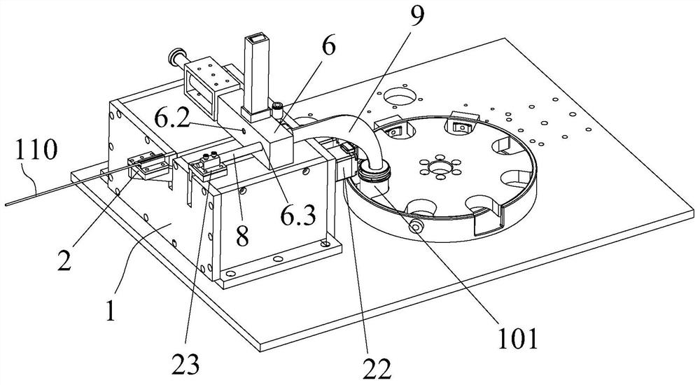
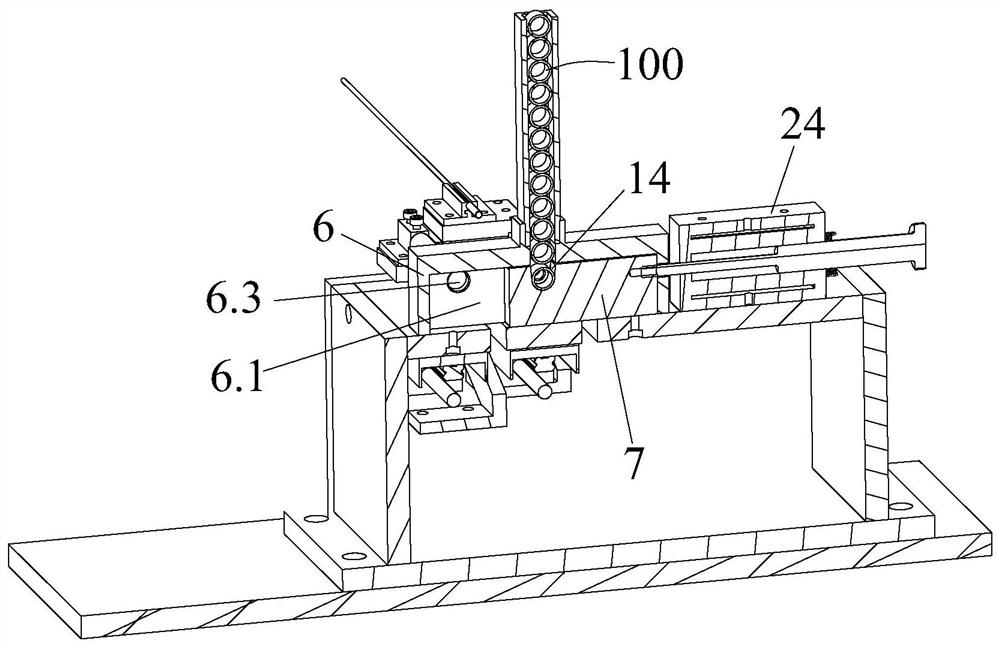
[0045] A positioning mechanism is provided on the base 1 for positioning the sample tube 100; when the end of the biopsy forceps 110 with the tissue sample is inserted into the sample tube 100; the separation mechanism is used to drive the tissue sample to detach from the biopsy forceps and attach to the sample tube 100. In the sample tube 100; specifically, when the sample tube 100 is positioned on the positioning structure, the forceps head end of the biopsy forceps 110 can be manually extended into the sample tube 100, but since the extension line of the biopsy forceps 110 is relatively soft in actual operation, The manual method is inefficient and difficult.

[0046] In this embodiment, in order to enable the forceps head end of the biopsy forceps 110 to smoothly extend into the sample tube 100 , as an improvement, a positioning base 2 for placing the forceps head end of the biopsy forceps 110 and a positioning base 2 for placing the forceps head end of the biopsy forceps 1...

Embodiment 2

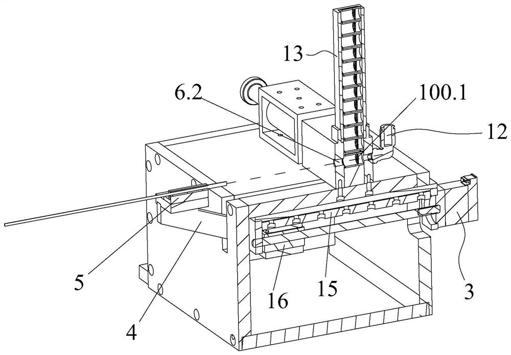
[0062] The mechanism of this embodiment is basically the same as that of the first implementation. The only difference is the structure of the separation mechanism:

[0063] like Figure 5 As shown, in this embodiment, the separation mechanism includes an air pipe 12 and an air blowing device 30, and the air blowing device 30 is arranged on the mounting block 6 at a position corresponding to the first station, specifically the position corresponding to the first through hole 6.2 , the air blowing device 30 is provided with a joint 30.1 connected to an external air pump. One end of the air pipe 12 is connected to the other end of the mounting block 6 at a position symmetrical to the first station, specifically a position symmetrical to the first through hole 6.2, and the other end of the air pipe 12 is directly connected to the external environment. In this structure, there are also a plurality of ventilation holes 31 on the side wall of the mounting block 6 for connecting the...

Embodiment 3

[0065] This embodiment is basically the same as the mechanism of Implementation 1, the only difference is the structural form of the separation mechanism:

[0066] Specifically, the separating mechanism includes a stroking head (not shown in the figure), which is used to strobe the tissue samples on the biopsy forceps directly into the sample collection container 101 .


PUM


Abstract

The invention discloses a tissue specimen collection mechanism. The tissue specimen collection mechanism comprises a base that is provided with a positioning mechanism for positioning a sample tube; aseparating mechanism by which when one end, with tissue specimens, of biopsy forceps extends into the sample tube, the tissue specimens are driven to be separated from the biopsy forceps and attachedon the sample tube; and a conveying mechanism used for driving the sample tube with the tissue specimens to automatically fall into a specimen bottle preset on the base so as to realize automatic collection of the tissue specimens. The automatic tissue specimen collection mechanism of the present invention is simple in structure, achieves automatic separation of tissue specimens from the biopsy forceps, and allows the separated tissue specimens to enter the specimen bottle without manual separation in the intermediate process. The automatic tissue specimen collection mechanism of the presentinvention has high collection efficiency.

Description

technical field [0001] The invention relates to the technical field of living body sampling, in particular to a tissue sample collection mechanism and a sample tube. Background technique [0002] With the development of modern science and technology, the endoscope has been completely reformed and uses optical fibers. In 1964, Japan successfully developed a biopsy forceps device for fiberoptic endoscopes. This kind of biopsy forceps can obtain suitable pathological materials and is less dangerous. Endoscopy in the modern sense is gradually formed with the realization of fiber optic endoscope. In November 2002, the world's first "high-definition endoscopy system" was born, and the concept of endoscopy has undergone great changes. It integrates cutting-edge imaging technology, and the image accuracy provided makes it possible to diagnose extremely small lesions. [0003] However, in the current biopsy device, after the biopsy is completed, the tissue sample needs to be manua...

Claims


Application Information

Patent Timeline
Patent Type & Authority Applications(China)
IPC IPC(8): A61B10/04A61B10/06A61B10/00
CPCA61B10/0096A61B10/04A61B10/06
Inventor 金之凌
Owner 宁波之凌智能科技有限责任公司
Why Eureka
Try Eureka