

Wind power ring blank capable of reducing stress concentration and preparation process thereof
A technology of stress concentration and preparation process, which is applied in the field of wind power parts, can solve the problems affecting the stability of wind power equipment, large stress concentration of wind power ring parts, etc., and achieve the effect of reducing stress concentration, reducing stress concentration and tight connection
- Summary
- Abstract
- Description
- Claims
- Application Information
AI Technical Summary
Problems solved by technology
Method used
Image

Examples
Embodiment Construction
[0030] The following will clearly and completely describe the technical solutions in the embodiments of the present invention with reference to the accompanying drawings in the embodiments of the present invention. Obviously, the described embodiments are only some, not all, embodiments of the present invention. Based on the embodiments of the present invention, all other embodiments obtained by persons of ordinary skill in the art without making creative efforts belong to the protection scope of the present invention.
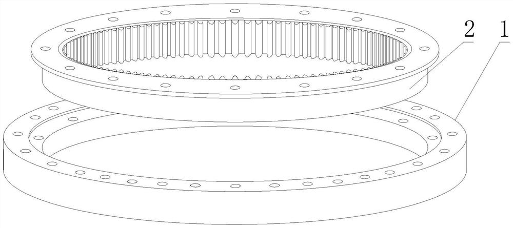
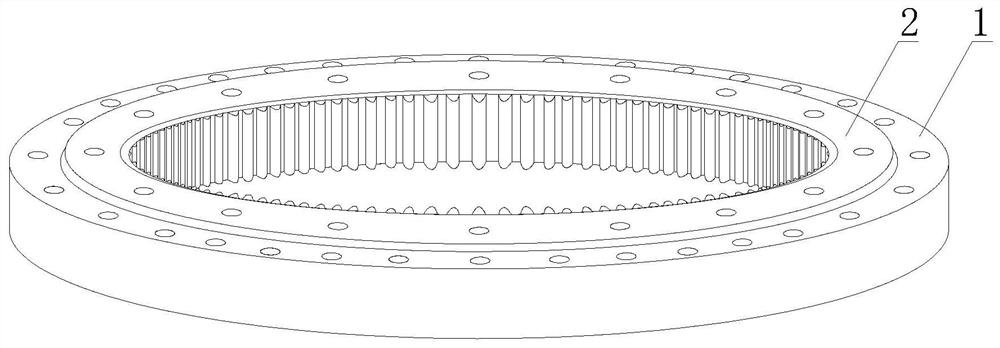
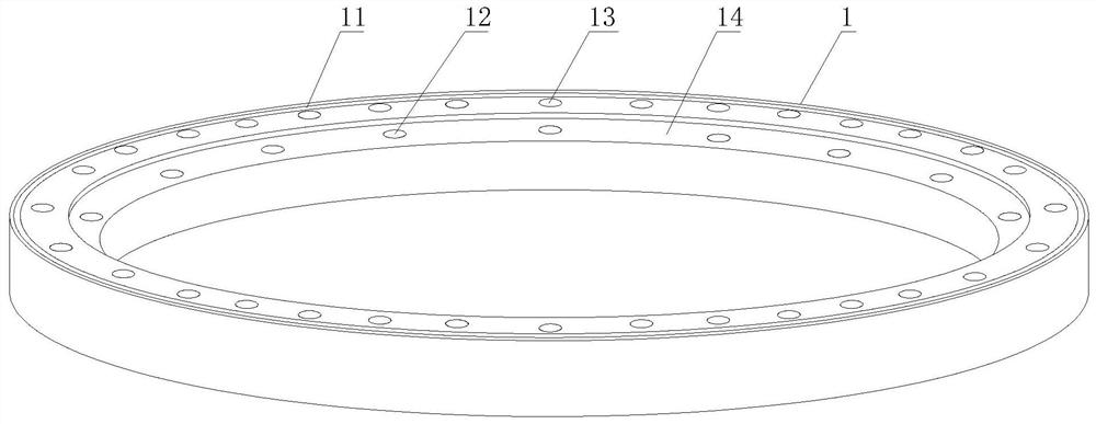
[0031] see Figure 1-Figure 4 , a wind power ring blank that reduces stress concentration, including a ring body 1 and an inner sleeve 2, the inner sleeve 2 is assembled on the inner side of the ring body 1, and the connection between the inner sleeve 2 and the inner wall of the ring body 1 is as follows Interference fit, so that the assembled wind power ring blanks are more tightly connected. The inner side of the inner sleeve 2 is provided with evenly distri...
PUM
| Property | Measurement | Unit |
|---|---|---|
| Surface roughness | aaaaa | aaaaa |
Abstract
Description
Claims
Application Information