
A self-balancing double-shock wave cam double-stage parallel planar movable gear reducer

A movable-tooth reducer and self-balancing technology, which is applied in the field of movable-tooth transmission, can solve problems such as complex reduction ratio calculation methods and reduce mechanism eccentric quality, and achieve flexible and changeable configuration methods, simple and compact structure, and wide reduction ratio range Effect

Active Publication Date: 2021-12-21
YANSHAN UNIV
View PDF8 Cites 0 Cited by
  • Summary
  • Abstract
  • Description
  • Claims
  • Application Information

AI Technical Summary

Problems solved by technology

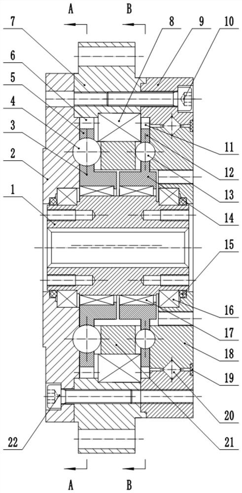
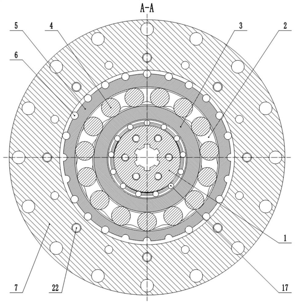
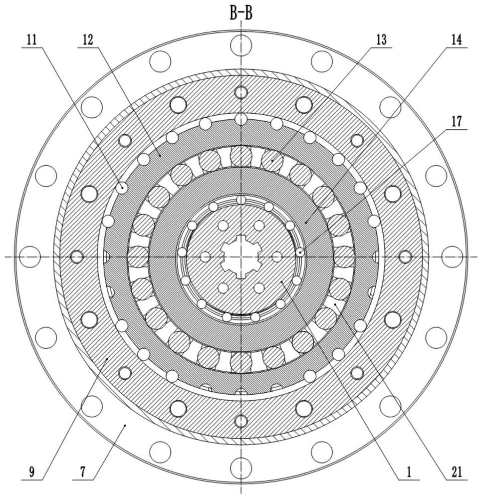
[0005] In view of the above problems, the present invention provides a self-balancing double-shock wave cam double-stage parallel planar movable gear reducer. form, the calculation method of the reduction ratio is more complicated, but it has a wider range of reduction ratios. At the same time, under the same reduction ratio, this configuration has more movable teeth, and the rated load and impact resistance of the whole machine are significantly improved. Lifting; the form of double shock cams is adopted, that is, the movable teeth mesh with the inner and outer two shock cams at the same time, thereby realizing the effect of full tooth meshing force transmission; there is a roller groove on the outer side of the outer shock cam, which is used It is used to place the roller counterweight, thereby reducing the eccentric mass of the whole mechanism. At the same time, the roller provides the function of the bearing, which increases the stability of the transmission mechanism.

Method used


Image

  • A self-balancing double-shock wave cam double-stage parallel planar movable gear reducer
  • A self-balancing double-shock wave cam double-stage parallel planar movable gear reducer
  • A self-balancing double-shock wave cam double-stage parallel planar movable gear reducer

Examples


Embodiment Construction

[0034] The technical solutions of the present invention are further specifically described below by way of examples and in connection with the accompanying drawings.

[0035] Figure 1-15 Preferred embodiments of the present invention, taken symbolic pictograms method employed by the symbol "S" representative of the track center strings, showing the movable toothed straight groove, S H together with the corresponding symbol "H", plus shock and external cams, constitute a sub-set of viable toothing. A first center wheel has a first movable teeth meshing with the second movable teeth meshing second sun gear, a third and a fourth sub live live toothing meshing teeth on the third sun gear. Four movable teeth meshing means are used for transmission of two, arranged in the form of a combination of symbols with the expression, in accordance with the present invention, the sub-arrangement permutations engagement total "SHSH", "SHHS", " HSSH "and" HSHS "four kinds of transmission type.

[...


PUM


Abstract

The invention provides a self-balancing double-shock wave cam double-stage parallel planar movable gear reducer, which includes an input shaft, a first center wheel, a first inner shock cam, a first movable tooth, a first outer shock cam, a first Roller, second roller, second outer shock cam, second movable tooth, second inner shock cam, second center wheel, third center wheel, etc. Its transmission mechanism adopts double-stage parallel connection, and the calculation method of reduction ratio is more complicated, but it has a wider range of reduction ratio. At the same time, under the same reduction ratio, this configuration has more movable teeth, and the rated The load and impact resistance have been significantly improved; the form of double shock cams is adopted, that is, the movable teeth mesh with the inner and outer shock cams at the same time, thereby realizing the effect of full tooth meshing force transmission; the outer shock cams are opened outside A circle of roller grooves is used to place the roller counterweight, thereby reducing the eccentric mass of the entire mechanism. At the same time, the rollers provide the function of bearings and increase the stability of the transmission mechanism.

Description

Technical field [0001] The present invention relates to tooth transmission technology, and particularly relates to a self-balancing dual two-stage shock cam plane parallel teeth reducer. Background technique [0002] my country has the world's largest industrial robot sitting on the market, it requires a lot of high-precision reducer year, but the high-end reducer areas dependent on imports, no domestic alternative. Follow the existing three traditional drive technology, ie planetary gear, RV and harmonic drive transmission, it is difficult to achieve a breakthrough technology in accordance with its original route and break the market monopoly. In this regard, different from the traditional study of three transmission technology tooth drive technology, it is very necessary. [0003] Tooth drive a wide variety, this team is mainly engaged in the research sinusoidal sliding transmission, relying on key national research and development programs, special intelligent robot in the "ne...

Claims


Application Information

Patent Timeline
Patent Type & Authority Patents(China)
IPC IPC(8): F16H49/00F16H57/023F16H57/021
CPCF16H49/001F16H57/023F16H57/021
Inventor 许立忠闫济东
Owner YANSHAN UNIV
Learn More