
Composite lens, manufacturing method thereof and infrared detector

A compound lens and technology of manufacturing method, which is applied in the field of optics, can solve problems affecting the imaging effect of the compound lens, and achieve the effect of improving the imaging effect and high tolerance

Active Publication Date: 2020-12-18
YANTAI RAYTRON TECH
View PDF17 Cites 5 Cited by
  • Summary
  • Abstract
  • Description
  • Claims
  • Application Information

AI Technical Summary

Problems solved by technology

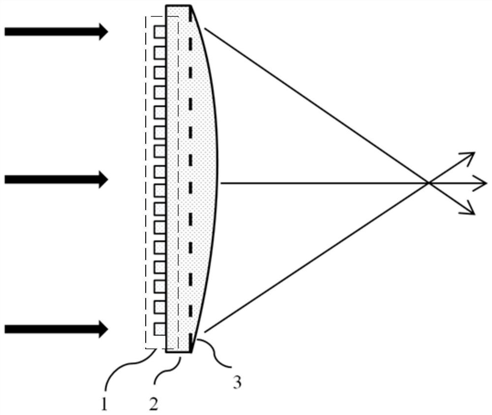
Currently, compound lenses based on metasurfaces figure 1 As shown, a metasurface structure array is distributed on one surface of the substrate, and the ball lens formed by photoresist is covered on the metasurface. Once the ball lens is processed, the processing error generated cannot be corrected by adjusting the metasurface structure array. Thus affecting the imaging effect of the compound lens

Method used


Image

  • Composite lens, manufacturing method thereof and infrared detector
  • Composite lens, manufacturing method thereof and infrared detector
  • Composite lens, manufacturing method thereof and infrared detector

Examples


specific Embodiment approach

[0086] As a specific implementation, the composite lens 3 may also include:

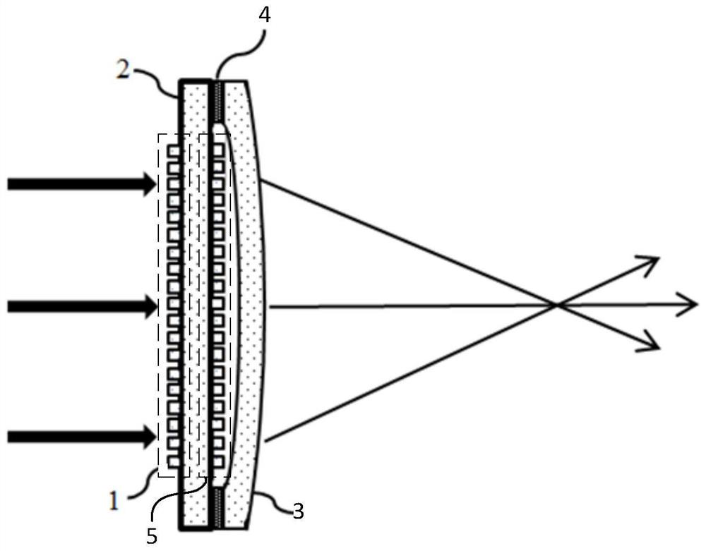
[0087] The bonding layer is used to connect the lens 3 and the first surface of the substrate 2 . by figure 2 The composite lens 3 in , is described as an example, that is, a bonding layer is provided between the substrate 2 and the lens 3 .

[0088] Please refer to image 3 , image 3 It is a structural schematic diagram of another compound lens 3 provided in the embodiment of the present application. When the ball lens 3 is a biconvex spherical ball lens 3, the compound lens 3 also includes:

[0089] The second metasurface structure array 5 located on the first surface of the substrate 2, the second metasurface structure array 5 is located in the cavity formed by the biconvex spherical ball lens 3 and the first surface, Wherein, the second metasurface structure array 5 includes a plurality of metasurface structure units.

[0090] In this application, the bonding layer 4 is not limited, and ca...


PUM


Abstract

The invention discloses a compound lens. The compound lens comprises: a substrate; a lens located on the first surface of the substrate; and a first metasurface structure array which is arranged on the second surface of the substrate according to the face type machining error of the lens and comprises a plurality of metasurface structure units, wherein the first surface is opposite to the second surface. The compound lens comprises the substrate, the lens and the first metasurface structure array, the lens and the first metasurface structure array are located on the first surface and the second surface of the substrate respectively, and due to the fact that the lens and the first metasurface structure array are located on the two different surfaces of the substrate, after the lens is manufactured, the first metasurface structure array can be set according to the surface type of the lens; in addition, due to the fact that the first metasurface structure array can be arranged after the lens is manufactured, the tolerance to machining errors is extremely high. The invention further provides a manufacturing method of the composite lens and an infrared detector with the advantages.

Description

technical field [0001] The present application relates to the field of optical technology, in particular to a composite lens, a manufacturing method thereof, and an infrared detector. Background technique [0002] With the development of optical technology, large-scale integration, miniaturization and functional diversity of optical devices have become new development goals. [0003] Due to the large volume and weight of traditional lenses, compound lenses based on metasurfaces emerge as the times require. A metasurface is a two-dimensional optical plane. By arranging subwavelength structures on the metasurface in a specific way, the parameters such as the amplitude, phase, and polarization of incident electromagnetic waves can be flexibly adjusted, breaking through the electromagnetic properties of traditional optical lenses. Currently, compound lenses based on metasurfaces figure 1 As shown, a metasurface structure array is distributed on one surface of the substrate, an...

Claims


Application Information

Patent Timeline
IPC IPC(8): G02B3/00G03F7/00G02B27/00G01J5/10
CPCG02B3/00G03F7/0005G02B27/0012G01J5/10G01J2005/106G01J5/0806G02B1/002G02B27/0025G02B3/08G02B3/0018G02B2003/0093
Inventor 丁心宇王鹏李君宇虞传庆
Owner YANTAI RAYTRON TECH
Learn More