Optical lens, camera module and electronic equipment
An optical lens and lens technology, which is applied in optics, optical components, instruments, etc., can solve the problems that the presentation of long-distance details cannot be satisfied at the same time, the resolution of the test camera is low, and there are driving risks, so as to achieve miniaturization design , improve the resolution and depth of field range, and improve the effect of imaging clarity
- Summary
- Abstract
- Description
- Claims
- Application Information
AI Technical Summary
Problems solved by technology
Method used
Image
Examples
no. 1 example
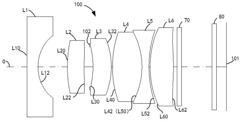
[0100] The schematic structural diagram of the optical lens 100 disclosed in the first embodiment of the present application is as follows: figure 1 As shown, the optical lens 100 includes a first lens L1, a second lens L2, a third lens L3, a fourth lens L4, a fifth lens L5, a sixth lens L6, a fourth lens L4, a fifth lens L5, a sixth lens L6, Infrared filter 70 and protective glass 80 .
[0101] The first lens L1 has a negative refractive power, including a first object side L10 and a first image side L12, and the second lens L2 has a positive refractive power, including a second object side L20 and a second image side L22. The third lens L3 has a positive refractive power, and includes a third object side L30 and a third image side L32. The fourth lens L4 has a positive refractive power and includes a fourth object side L40 and a fourth image side L42. The fifth lens L5 has negative refractive power, and includes a fifth object side L50 and a fifth image side L52. The sixt...
no. 2 example
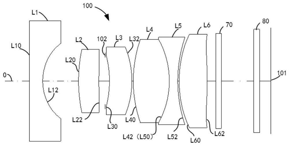
[0122] Please refer to image 3 , image 3 It is a schematic structural diagram of the optical lens 100 according to the second embodiment of the present application. The optical lens 100 includes a first lens L1 , a second lens L2 , a third lens L3 , a fourth lens L4 , a fifth lens L5 , a sixth lens L6 , and an infrared filter, which are sequentially arranged along the optical axis O from the object side to the image side. Sheet 70 and protective glass 80 .
[0123] It can be understood that the refractive power of each lens of the optical lens 100 in the second embodiment, the shape of the object side surface and the image side surface of each lens are consistent with those shown in the optical lens 100 of the first embodiment, and will not be repeated here. .
[0124] In the second embodiment, the ratio of each relational expression satisfied by the optical lens 100 can be referred to as shown in Table 4 below:
[0125] Table 4
[0126]
[0127]
[0128] Specific...
no. 3 example
[0138] Please refer to Figure 5 , Figure 5 A schematic structural diagram of the optical lens 100 according to the third embodiment of the present application is shown. The optical lens 100 includes a first lens L1 , a second lens L2 , a third lens L3 , a fourth lens L4 , a fifth lens L5 , a sixth lens L6 , and an infrared filter, which are sequentially arranged along the optical axis O from the object side to the image side. Sheet 70 and protective glass 80 .
[0139] It can be understood that the refractive power of each lens, the shape of the object side surface and the image side surface of each lens of the optical lens 100 in the third embodiment are consistent with those shown in the optical lens 100 of the first embodiment, and will not be repeated here. .
[0140] In the third embodiment, the ratio of each relational expression satisfied by the optical lens 100 can be referred to as shown in Table 7 below:
[0141] Table 7
[0142] relational ratio ...
PUM
 Abstract
Description
Claims
Application Information
 - R&D
- Intellectual Property
- Life Sciences
- Materials
- Tech Scout
- Unparalleled Data Quality
- Higher Quality Content
- 60% Fewer Hallucinations
Browse by: Latest US Patents, China's latest patents, Technical Efficacy Thesaurus, Application Domain, Technology Topic, Popular Technical Reports.
© 2025 PatSnap. All rights reserved.Legal|Privacy policy|Modern Slavery Act Transparency Statement|Sitemap|About US| Contact US: help@patsnap.com


