Converter system for retired power battery, control method thereof and storage medium

A power battery and power flow system technology, which is applied to the arrangement of multiple synchronous batteries, the adjustment of electric variables, and the protection of battery overheating. Reasonability and other issues, to achieve the effect of improving capacity utilization, improving operation and maintenance convenience, and high stability

Pending Publication Date: 2020-12-18
CHINA SOUTHERN POWER GRID COMPREHENSIVE ENERGY
View PDF6 Cites 5 Cited by
  • Summary
  • Abstract
  • Description
  • Claims
  • Application Information

AI Technical Summary

Problems solved by technology

However, since retired power batteries come from different models of electric vehicles, the technical standards of each retired power battery are different. Each is different, so when multiple decommissioned power batteries form a battery pack, it is prone to the problem of unbalanced work of each decommissioned power battery
In the existing technology, due to the unreasonable structure of the inverter system, it is impossible to effectively deal with this unbalanced problem, and even the loop current of several hundred amps in the decommissioned power battery may cause the line to burn out

Method used


Image

  • Converter system for retired power battery, control method thereof and storage medium
  • Converter system for retired power battery, control method thereof and storage medium
  • Converter system for retired power battery, control method thereof and storage medium

Examples


Embodiment Construction

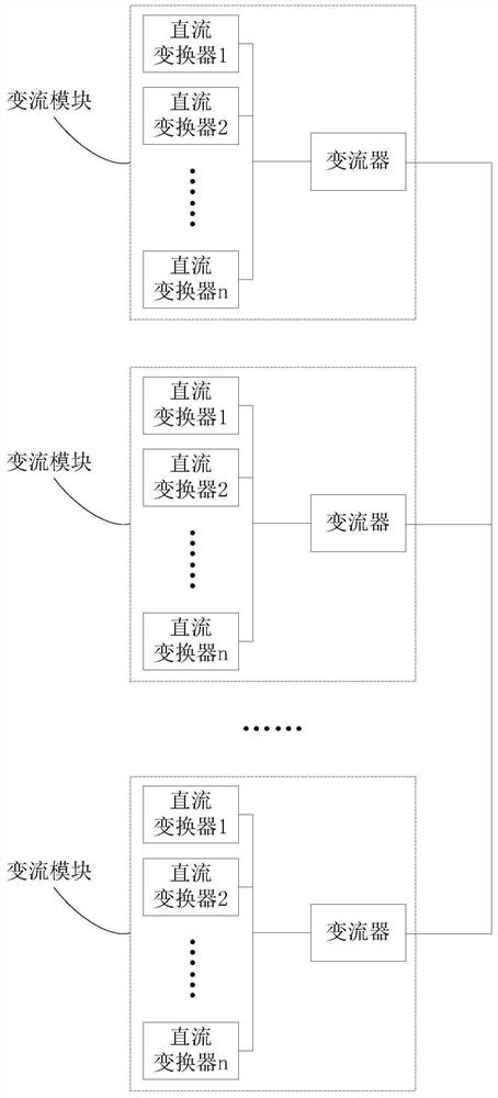
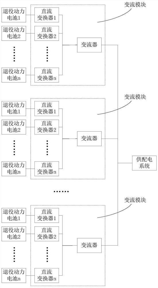
[0032] In this example, if figure 1 As shown, the converter system includes a plurality of converter modules, each converter module includes a converter and n DC converters, and the converters are connected to the DC converters. In this embodiment, except for parameters such as the power of the converter, each converter module is different or not completely the same, and its circuit structure and working principle may be the same, so this embodiment can describe one of the converter modules. When the converter system is used, the converter system can be connected with the decommissioned power battery and the power supply and distribution system respectively. The connection structure is as follows: figure 2 shown.

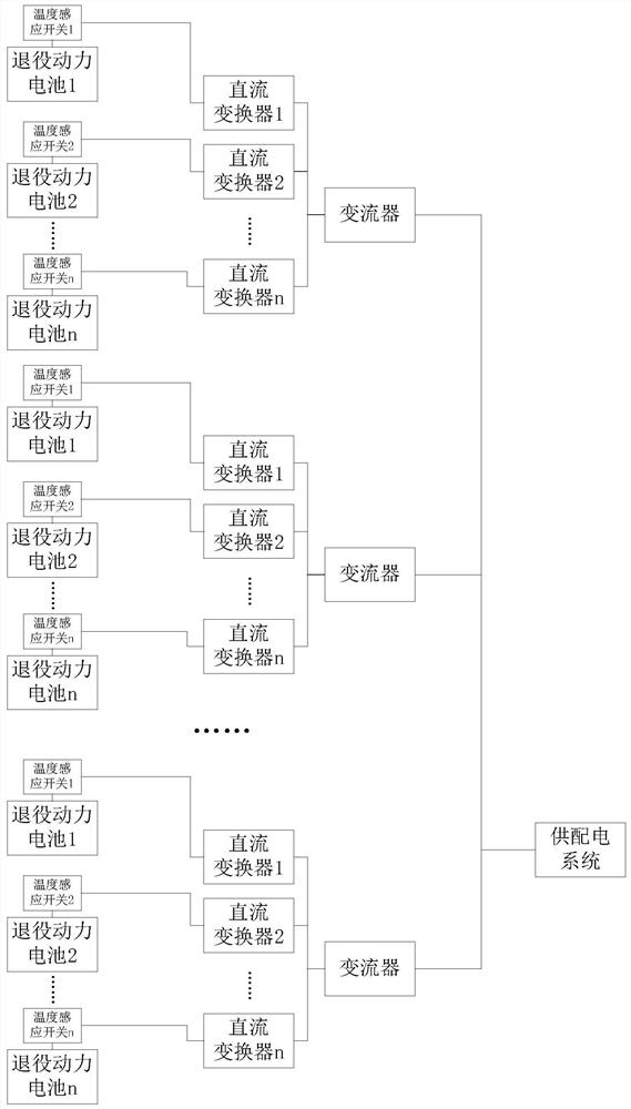
[0033] refer to figure 2 , one end of the DC converter is connected to the decommissioned power battery, that is, a DC converter is connected to a decommissioned power battery. figure 2 There are n decommissioned power batteries, but there may be less than n d...


PUM


Abstract

The invention discloses a converter system for a retired power battery, a control method thereof, and a storage medium; the converter system comprises a direct current converter, a converter and a control module, one end of the direct current converter is used for being connected with the retired power battery, and one end of the converter is connected to a power supply and distribution system; the other end of the converter is connected with the other end of the direct-current converter, and the control module acquires state parameters of the retired power battery and controls working parameters of the converter and the direct-current converter according to the state parameters. The converter system can be connected to a power supply and distribution system and different retired power batteries, so that an electric energy storage system is formed; through the improved topological structure of the converter system, each converter system can be independently discharged or charged, retired power batteries of different models or different state parameters can be prevented from interfering with each other, and the stability is high. The system and method is widely applied to the technical field of retired power battery utilization.

Description

technical field [0001] The invention relates to the technical field of utilization of decommissioned power batteries, in particular to a converter system for decommissioned power batteries, a control method and a storage medium thereof. Background technique [0002] Decommissioned power batteries refer to power batteries that have reached the decommissioning standard but still have residual capacity value, including batteries dismantled from electric vehicles. Existing technologies can use decommissioned power batteries as power energy storage systems, and use converter systems to connect decommissioned power batteries and power supply and distribution systems, so that decommissioned power batteries can store electricity from power supply and distribution systems, or supply power to power supply and distribution systems Transmission of electricity, so as to make full use of the value of decommissioned power batteries, which is conducive to environmental protection. However,...

Claims


Application Information

Patent Timeline
Patent Type & Authority Applications(China)
IPC IPC(8): H02J7/06H02J7/00H02J1/10H02J3/32H02H7/08H02H5/04H02M7/66H02M3/00
CPCH02J7/06H02J7/0018H02J7/0019H02J7/00047H02J7/00309H02J1/106H02J3/32H02H7/08H02H5/042H02M7/66H02M3/00H02J2207/20
Inventor 李达姜鹤郑海兴吴潮辉张剑锐龙慧林金
Owner CHINA SOUTHERN POWER GRID COMPREHENSIVE ENERGY
Why Eureka
Try Eureka