FPGA on-orbit debugging method for component flight verification

A component and debugging information technology, applied in the direction of electrical components, radio transmission systems, transmission systems, etc., can solve the problem of unable to collect internal dynamic information of on-orbit FPGA, unable to realize on-orbit FPGA positioning and resolution, and unable to perform remote debugging tests, etc. To achieve the effect of solving the inability to collect internal dynamic information, broaden detection methods, and improve on-orbit life

Active Publication Date: 2020-12-18
北京轩宇空间科技有限公司
View PDF4 Cites 0 Cited by
  • Summary
  • Abstract
  • Description
  • Claims
  • Application Information

AI Technical Summary

Problems solved by technology

[0006] However, this method has the following problems: At present, the online reconstruction of components through the "MCU+FPGA" method can only realize the function of remote program download, and cannot perform remote debugging and testing.
Once an on-orbit FPGA fa

Method used


Image

  • FPGA on-orbit debugging method for component flight verification
  • FPGA on-orbit debugging method for component flight verification
  • FPGA on-orbit debugging method for component flight verification

Examples


Embodiment 1

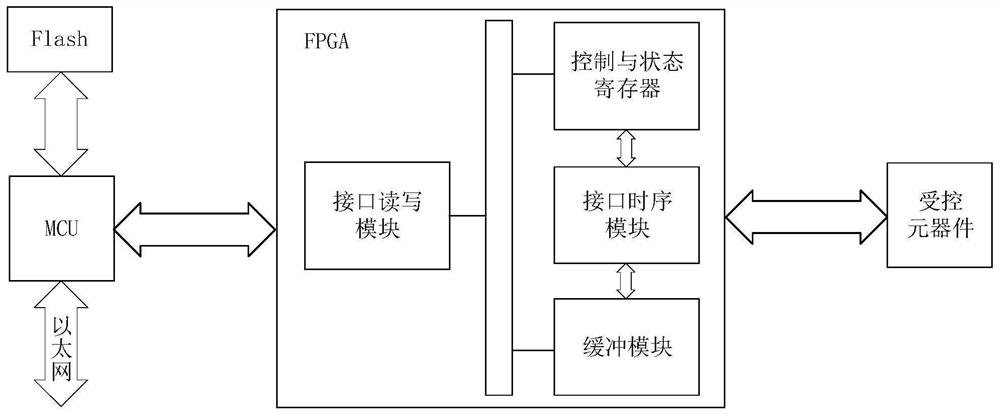
[0033] Debugging methods include

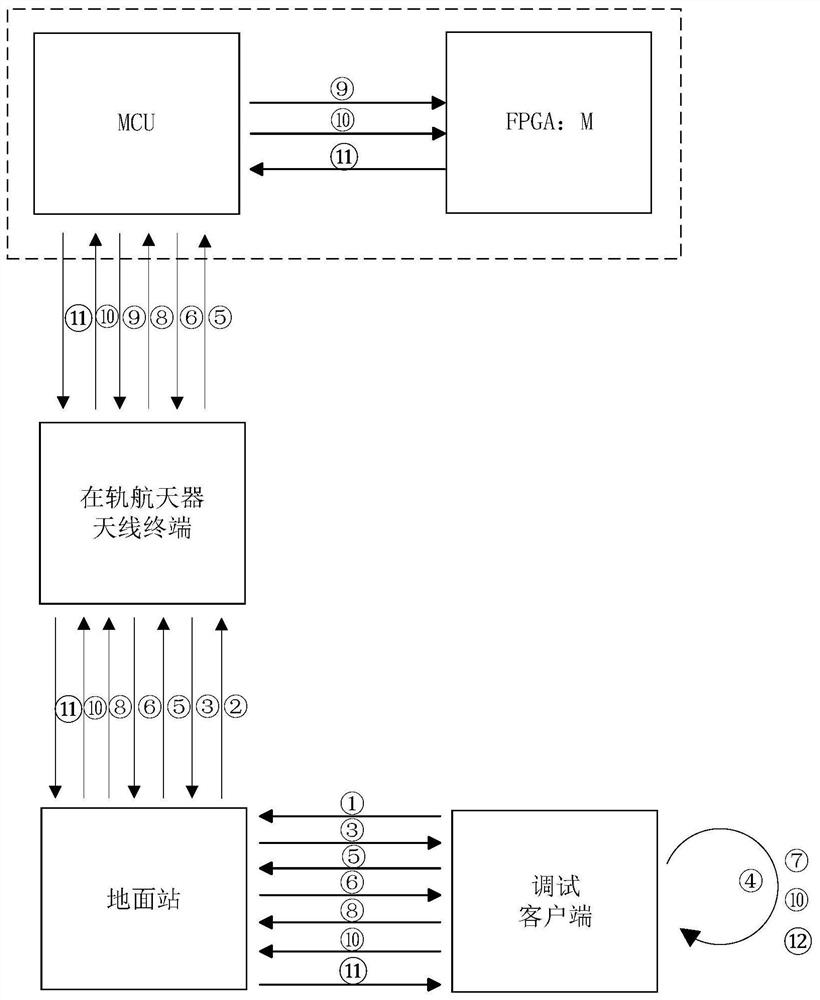
[0034] S1: The debugging client is connected to the ground station through a cable, and the ground station initiates a transmission request to the antenna terminal of the on-orbit spacecraft through the satellite-ground communication link. After waiting for the communication to be established, the ground terminal initiates a FPGA download or debugging information transmission request;

[0035] S2: After receiving the request information, the antenna terminal of the in-orbit spacecraft transmits the connection establishment information to the MCU through Ethernet;

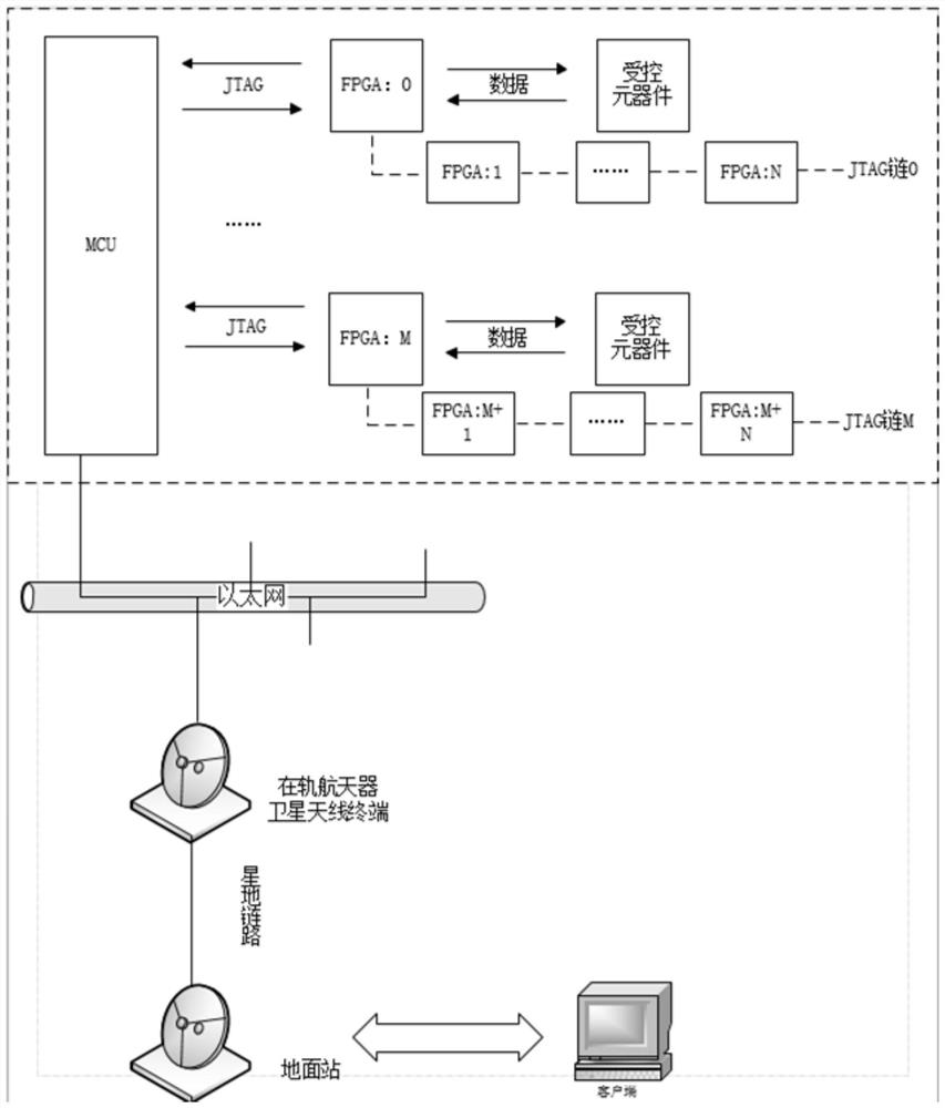
[0036] S3: MCU receives and parses the Ethernet data packet containing FPGA download or debugging information, and then sends the information to FPGA through a custom JTAG link;

[0037] S4: After the FPGA receives the download or debug information request information from the ground station, it returns the response response information and handshake data to the MCU;

[0038] S5: ...

Embodiment 2

[0055] Preferably, in the steps S1, S2, S3, S4, S5, S6, S7, the method can realize the remote download and remote debugging of the FPGA on the track, and support the download of multiple FPGA devices of one or more JTAG chains and debugging;

[0056] Preferably, the connection established between the ground terminal and the FPGA under test in orbit includes "ground test terminal - ground communication terminal - antenna terminal on orbit spacecraft - control MCU on orbit - FPGA under test on orbit "The entire communication link, after research and testing, the delay of the link is within 100ms, which can meet the response time requirements of the ground debugging software.

[0057] Preferably, the remote FPGA debugging method is not only applicable to satellite-ground remote debugging, but also applicable to astronauts' in-orbit cabin debugging (such as debugging the external terminal FPGA in a space station) or ground equipment debugging tests.


PUM


Abstract

The invention discloses an FPGA on-orbit debugging method for component flight verification, and the method comprises the following steps: S1, enabling a debugging client to be connected with a groundstation through a cable, enabling the ground station to initiate a transmission request to an on-orbit spacecraft antenna terminal through a satellite-ground communication link, waiting for the establishment of communication, and then the ground terminal initiating an FPGA downloading or debugging information transmission request; S2, after receiving the request information, the on-orbit spacecraft antenna terminal transmitting the connection establishment information to the MCU through the Ethernet; S3, the MCU receiving and analyzing an Ethernet data packet containing FPGA downloading or debugging information, and then sending the information to the FPGA through a user-defined JTAG link; S4, after receiving the information of the downloading or debugging information request ground station, the FPGA returning response information and handshake data to the MCU; and S5, after the MCU receives response information and handshake data returned by the FPGA, the information being transmitted to the on-orbit spacecraft antenna terminal through the Ethernet.

Description

technical field [0001] The present invention relates to a remote debugging method of FPGA oriented to flight test of components, aiming at the requirements of FPGA on-orbit debugging required for applications such as component flight verification, this method proposes on-orbit debugging based on satellite-ground link and MCU remote control method. There is no need to add a separate JTAG hardware link connection, and the relay processing of data and control signals is realized through the MCU, which solves the feasibility problem of on-orbit FPGA debugging, downloading and monitoring under unattended conditions. Background technique [0002] MCU (Micro Control Unit) micro control unit, also known as single chip microcomputer (Single Chip Microcomputer) or single chip microcomputer, is to reduce the frequency and specifications of the central processing unit (Central Process Unit) appropriately, and the memory (memory), counter ( Timer), USB, A / D conversion, UART, PLC, DMA an...

Claims


Application Information

Patent Timeline
IPC IPC(8): H04B7/185H04B17/40
CPCH04B7/18519H04B17/40
Inventor 刘鸿瑾张绍林白星周游李天文王朋李宾王红霞焦聪苏博
Owner 北京轩宇空间科技有限公司
Why Eureka
Try Eureka