Automatic material pickup equipment for small hole stamping die

A technology for stamping dies and equipment, applied in the field of automatic material reclaiming equipment for small hole stamping dies, can solve the problems of insufficient safety and efficiency, the lack of large stamping process molds, and insufficient flexibility, and achieve high automation effects, good environmental protection effects, and flexibility high degree of effect

Active Publication Date: 2020-12-22
HUANGSHAN YUBO ELECTRICAL APPLICANCE
View PDF8 Cites 0 Cited by
  • Summary
  • Abstract
  • Description
  • Claims
  • Application Information

AI Technical Summary

Problems solved by technology

[0002]Small-hole stamping die is used as a stamping die for flat or formed parts of various metal materials. It is used for punching holes on flat or formed parts. It is widely used and is often used in In various light industry sectors, there are also some problems and shortcomings in the small hole stamping process, and some safety accidents often occur. Among these safety accidents, there is no great relationship with the stamping process and the mold itself. The main reason for these problems is the traditional Due to advanced stamping equipment and backward manual operation, with the advancement of science and technology, especially the development of PLC technology, and with the advancement of mechatronics technology, these problems will definitely be solved as soon as possible.
[0003] Now it is proposed to use equipment to automatically take materials, and the research on automation in the field of small hole stamping is also gradually carried out. At present, there is a lack of equipment for automatic material taking, and the existing equipment is large Most of the work content is single, but it is still not perfect enough to deal with various problems. For example, it can only pick and place finished products of the same material and thickness, but cannot pick and place finished products of different thicknesses. It is not flexible enough and the efficiency is not high. At the same time, waste will be generated during the stamping process, and some waste may remain on the formwork and need to be cleaned manually, which is not safe and efficient

Method used


Image

  • Automatic material pickup equipment for small hole stamping die
  • Automatic material pickup equipment for small hole stamping die
  • Automatic material pickup equipment for small hole stamping die

Examples


Embodiment Construction

[0029] The technical solutions of the present invention will be further described below in conjunction with the accompanying drawings and through specific implementation methods.

[0030] Wherein, the accompanying drawings are only for illustrative purposes, showing only schematic diagrams, rather than physical drawings, and should not be construed as limitations on this patent; in order to better illustrate the embodiments of the present invention, some parts of the accompanying drawings will be omitted, Enlarged or reduced, does not represent actual product size.

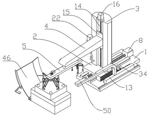
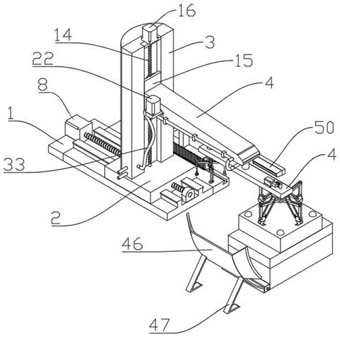
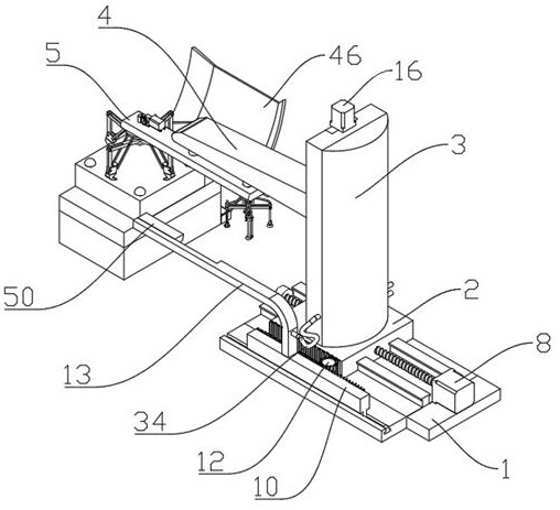
[0031] refer to figure 1 , figure 2 , image 3 and Figure 9 The shown automatic reclaiming equipment for small hole stamping dies includes a bottom plate 1, which is used to install parts and play a load-bearing role. The upper side of the bottom plate 1 is provided with a base 2, which is used to install parts and play a load-bearing role. , the base 2 is connected to the bottom plate 1 through a horizontal...


PUM


Abstract

The invention relates to the field of fire-fighting equipment, in particular to automatic material pickup equipment for a small hole stamping die. The equipment comprises a bottom plate; a base is arranged at the upper side of the bottom plate; the base is connected with the bottom plate through a horizontal driving assembly; a fixing base is fixedly arranged at the upper side of the base; a firstsliding block is arranged at one side of the fixing base and connected with the fixing base through a vertical driving assembly; a moving arm is fixedly arranged on the sliding block; a switching rodis rotationally arranged at one end of the moving arm; a first power assembly for driving the switching rod to rotate is arranged in the moving arm; a gripper assembly and a suction cup assembly arearranged at the two ends of the switching rod correspondingly; a blowing mechanism is arranged at the upper side of the bottom plate; an arc-shaped plate matched with the blowing mechanism is arrangedat one side of the switching rod; two bending rods are fixedly arranged at the lower side of the arc-shaped plate; and a collecting box is arranged at the lower end of the arc-shaped plate. The automatic material pickup equipment can be used for automatic material pickup of the small hole stamping die, materials with different thicknesses can be picked up and placed, the working efficiency is high, meanwhile, a certain sweeping function is achieved on waste generated after stamping, and the waste can be collected.

Description

technical field [0001] The invention relates to the field of automatic material retrieving, in particular to an automatic material reclaiming device for a small hole stamping die. Background technique [0002] As a stamping die for flat or formed parts of various metal materials, small hole punching dies are used for punching holes on flat or formed parts. They are widely used and are often used in various light industry sectors. There are also some problems and problems in small hole punching. Disadvantages, some safety accidents often occur. Among these safety accidents, there is no great relationship with the stamping process and the mold itself. The main cause of these problems is caused by traditional stamping equipment and backward manual operations. With the development of science and technology The progress of the PLC technology, especially the development of PLC technology, along with the progress of the mechatronics technology, these problems will definitely be sol...

Claims


Application Information

Patent Timeline
Patent Type & Authority Applications(China)
IPC IPC(8): B21D43/10B21D43/18B21D45/02
CPCB21D43/105B21D43/18B21D45/02B21D45/003
Inventor 赵淑英庄静梅
Owner HUANGSHAN YUBO ELECTRICAL APPLICANCE
Why Eureka
Try Eureka