Tail end position compensation method based on robot joint angle compensation and application of tail end position compensation method

A technology for robot joint and angle compensation, which is applied in the directions of manipulators, program-controlled manipulators, joints, etc., and can solve problems such as the inability to obtain the expected compensation effect.

Inactive Publication Date: 2020-12-22
SOUTH CHINA UNIV OF TECH
View PDF6 Cites 6 Cited by
  • Summary
  • Abstract
  • Description
  • Claims
  • Application Information

AI Technical Summary

Problems solved by technology

[0006] After kinematic error compensation, whether the compensation of the robot’s non-geometric error is effective, especially the robot’s end error caused by the random error of the robot’s kinema

Method used


Image

  • Tail end position compensation method based on robot joint angle compensation and application of tail end position compensation method
  • Tail end position compensation method based on robot joint angle compensation and application of tail end position compensation method
  • Tail end position compensation method based on robot joint angle compensation and application of tail end position compensation method

Examples


Embodiment

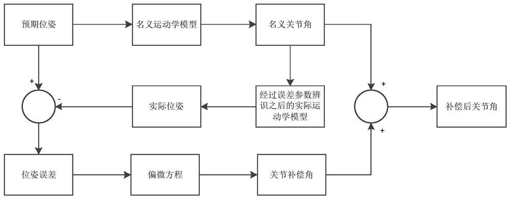
[0080] Such as figure 1 As shown, this embodiment provides a method for end position compensation based on robot joint angle compensation, including the following steps:

[0081] First, establish the MD-H kinematics model of the six-degree-of-freedom robot. The establishment of the coordinate system is the selection of the direction of the coordinate axis and the origin. The method for establishing the reference coordinate system of the joint axis in the D-H model is as follows:

[0082] (1) Establishment of z-axis direction

[0083] The coordinate system established at joint i is named coordinate system i-1. If joint i is a rotation axis joint, the z-axis direction is consistent with the axis of the joint rotation axis; if joint i is a moving joint, set its moving direction as the z-axis axis direction;

[0084] (2) Establishment of the origin of the coordinate system and the direction of the x-axis

[0085] There may be three geometric relationships between the axes of tw...


PUM


Abstract

The invention discloses a tail end position compensation method based on robot joint angle compensation and application of the tail end position compensation method. The method comprises the steps that a kinematics model of a robot and an error model of the robot are constructed; an optimal individual is output to serve as an initial solution of a tabu search algorithm by adopting a fitness function; robot kinematics error model identification is conducted by adopting the tabu search algorithm; and robot tail end error compensation is realized by using a Newton-Raphson iteration method. Accurate identification of model errors is realized by using global search capability of a genetic algorithm and local search capability of the tabu search algorithm so as to correct various parameters of arobot model, and Newton-Raphson iteration is applied to compensate for joint angle values of the robot multiple times so that the robot tail end can be positioned to the required position.

Description

technical field [0001] The invention relates to the technical field of robot kinematics calibration error compensation, in particular to an end position compensation method based on robot joint angle compensation and its application. Background technique [0002] Due to the deformation of the robot during manufacturing, assembly and loading, errors will inevitably occur, which have a greater impact on the positioning accuracy of the robot, thereby reducing the positioning accuracy of the robot. Modern robots require higher precision, reliability, and movement speed. In recent years, with the advancement of technology, especially the significant improvement of AC servo motor control technology, the repeatability of robots can be made very high, generally up to 0.05mm. The application of robots is not limited to traditional welding robots, handling robots and assembly robots, but has a wider range of applications in many fields such as medical service robots, underwater robots...

Claims


Application Information

Patent Timeline
IPC IPC(8): B25J9/16B25J17/00
CPCB25J9/1605B25J9/1664B25J17/00
Inventor 曹建城胥布工
Owner SOUTH CHINA UNIV OF TECH
Why Eureka
Try Eureka