Flexible mechanical claw and mechanical arm comprising same

A mechanical claw and flexible technology, applied in the field of intelligent robots, can solve problems such as joint joints with large load capacity, and achieve the effects of enhancing grasping stability, preventing finger eversion, and high spatial flexibility

Active Publication Date: 2020-12-22
BEIJING INSTITUTE OF TECHNOLOGYGY
View PDF9 Cites 3 Cited by
  • Summary
  • Abstract
  • Description
  • Claims
  • Application Information

AI Technical Summary

Problems solved by technology

However, the flexible mechanical grippers that have appeared in recent years are superior in terms of the degree of curvature of the gripper, the degree of fit with the target object, the stability and durability of the gripper, the maximum load capacity, the strength of the joint connection, and the development of underactuation. There are more or less deficiencies

Method used


Image

  • Flexible mechanical claw and mechanical arm comprising same
  • Flexible mechanical claw and mechanical arm comprising same
  • Flexible mechanical claw and mechanical arm comprising same

Examples


Embodiment 1

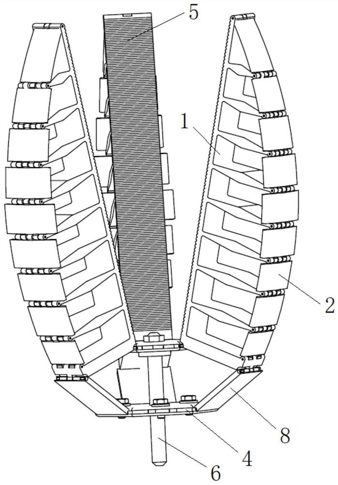
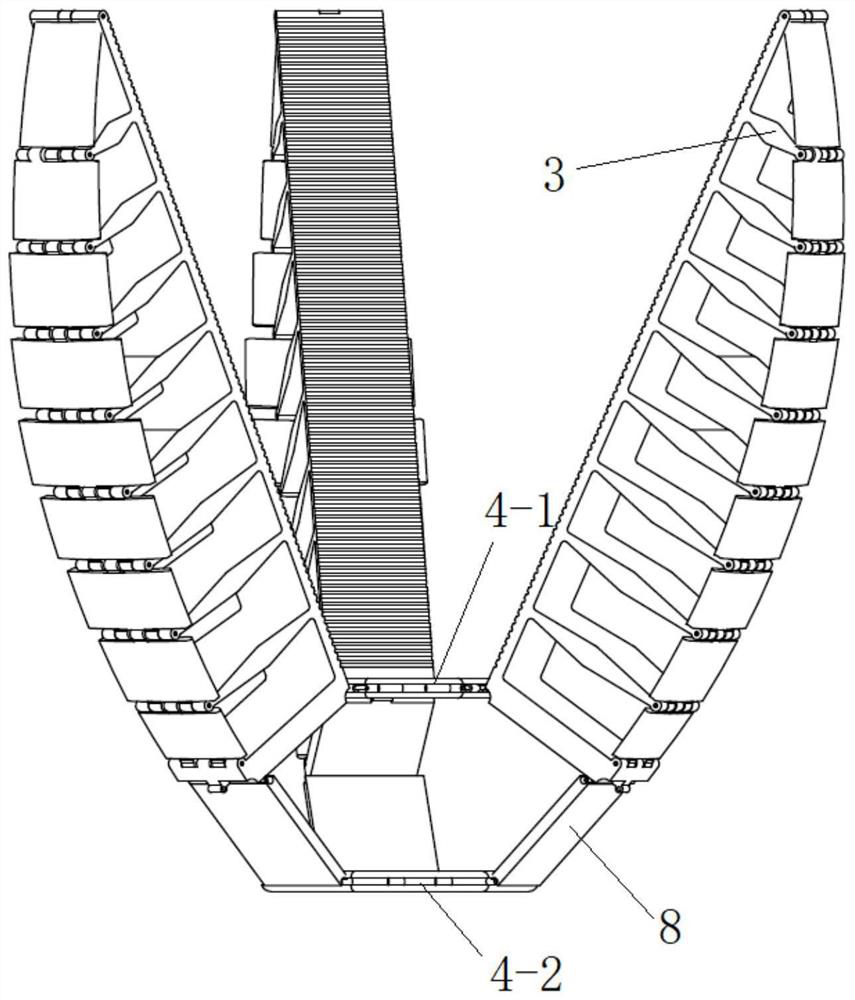
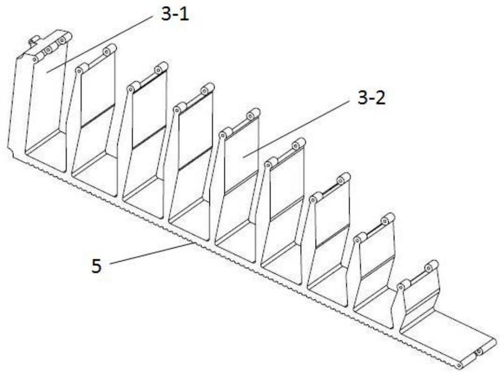
[0045] This embodiment provides a kind of flexible mechanical claw, refer to the attached Figure 1-2 , including: palm 4 and two or more fingers pinned to palm 4;

[0046] The palm 4 includes: a first plate 4-1, a second plate 4-2, a drive shaft 6 and a drive mechanism;

[0047] The first plate 4-1 and the second plate 4-2 are regular hexagonal plates, and the side length of the first plate 4-1 is smaller than the second plate 4-2, the first plate 4-1 and the second plate The materials of 4-2 are all made of metal materials;

[0048]The first plate 4-1 and the second plate 4-2 are arranged in parallel, and the six sides of the first plate 4-1 and the second plate 4-2 are parallel to each other; the drive shaft 6 passes through the Through the center of the first plate 4-1 and the second plate 4-2, and one end of the drive shaft 6 is fixedly connected with the first plate 4-1, and the other end of the drive shaft 6 is connected with the drive mechanism; when the drive mechan...

Embodiment 2

[0062] This embodiment provides a kind of flexible manipulator, refer to the attached Figure 5-7 , comprising: the mechanical claw and the arm body of Embodiment 1;

[0063] The arm body includes: wrist joint 9, forearm 10, upper arm 11, elbow joint 12 and shoulder joint 13;

[0064] The mechanical claw is installed on the front end of the forearm 10 through the wrist joint 9, the rear end of the forearm 10 is connected with the front end of the big arm 11 through the elbow joint 12, and the rear end of the big arm 11 is installed on the outside through the shoulder joint 13. On the supporting part; wherein, a supporting plate is fixed on the second plate 4-2 of the mechanical claw, and the supporting plate is installed on the wrist joint 9;

[0065] The wrist joint 9 has three degrees of freedom of rotation;

[0066] Both the elbow joint 12 and the shoulder joint 13 adopt double-slope bionic joints, which have two degrees of freedom of rotation;

[0067] Both the small ar...


PUM


Abstract

The invention discloses a flexible mechanical claw and a mechanical arm comprising the same. The mechanical claw comprises a palm and two or more fingers pinned to the palm, wherein each finger comprises an inner claw and an outer claw; each inner claw comprises integrally formed base plate and cross beams; two or more cross beams are located on the outer side surface of each base plate, and the tops of the cross beams and the end B of the base plate are separately provided with pin joints for being connected with the corresponding outer claw; each outer claw is a cambered surface plate whichis composed of two or more connecting plates and is bent to a set radian; and each connecting plate is separately pinned between two adjacent cross beams or between the end B of the corresponding baseplate and the adjacent cross beam of the base plate. The inner claws and the outer claws of the mechanical claw are made of flexible materials with different hardness, and the mechanical structure design of the inner claws and the outer claws is combined, so that the mechanical claw can well wrap a target object, and meanwhile, the mechanical claw has a very strong grabbing characteristic.

Description

technical field [0001] The invention belongs to the technical field of intelligent robots, and in particular relates to a flexible mechanical claw and a mechanical arm thereof. Background technique [0002] Mechanical claw, as the name implies, is a device that can replace human hands to perform a series of operations, mainly composed of hands and mechanisms for movement. To a certain extent, it can replace heavy labor by grabbing and carrying objects with a fixed program, and it can also be used in an environment that is harmful to the human body to protect personal safety. It is mainly used in machinery manufacturing, metallurgy, light industry, etc. Industrial sector. [0003] Most of the robotic claws at this stage have a single goal, generally only for one or two tasks. Again, the higher the flexibility of the gripper, the less damage it will cause to the target during work. Therefore, the traditional rigid mechanical gripper has limited its own application occasions...

Claims


Application Information

Patent Timeline
Patent Type & Authority Applications(China)
IPC IPC(8): B25J15/10B25J15/12B25J17/00B25J18/02B25J18/04B25J9/06
CPCB25J9/06B25J15/10B25J15/12B25J17/00B25J18/025B25J18/04
Inventor 苏伟李轶吕添彭旭东吴甲
Owner BEIJING INSTITUTE OF TECHNOLOGYGY
Why Eureka
Try Eureka