
Automatic gas-suction support column structure applied to twin-hull ship in small waterplane area

A technology of double-body and strut structure with small waterplane surface, applied in the directions of hydrodynamic characteristics/hydrostatic characteristics, hull, hull design, etc., can solve the problems of insignificant effect and can not significantly reduce the frictional resistance of the hull, and reduce the Design difficulty, simple structure, stable effect of gas-water mixture

Active Publication Date: 2020-12-22
HARBIN ENG UNIV
View PDF9 Cites 0 Cited by
  • Summary
  • Abstract
  • Description
  • Claims
  • Application Information

AI Technical Summary

Problems solved by technology

At present, the main means of hull drag reduction are surface coating and surface smoothness improvement, but the effect is not obvious and cannot significantly reduce the frictional resistance of hull

Method used


Image

  • Automatic gas-suction support column structure applied to twin-hull ship in small waterplane area
  • Automatic gas-suction support column structure applied to twin-hull ship in small waterplane area
  • Automatic gas-suction support column structure applied to twin-hull ship in small waterplane area

Examples


Embodiment Construction

[0025] The present invention will be further described in detail below in conjunction with the accompanying drawings and specific embodiments.

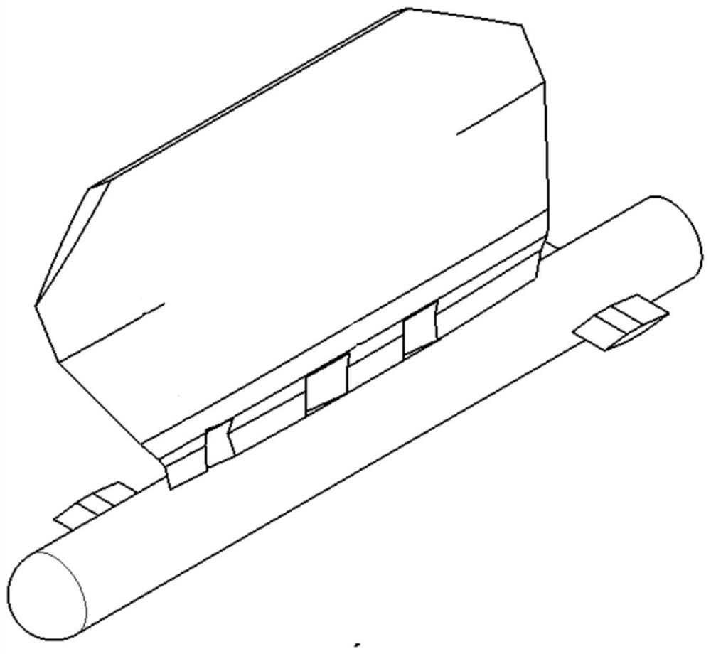
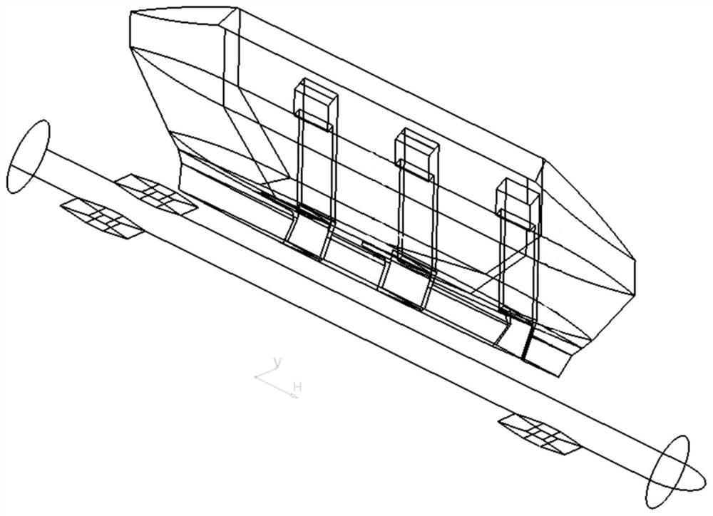
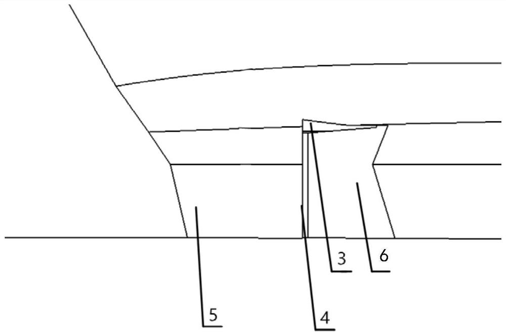
[0026] Combining Figure 1 to Figure 5 , an automatic air-breathing prop structure applied to small waterplane area catamarans according to the present invention, the structure includes 1-air inlet; 2-air inlet duct; 3-air outlet; 6-gas diversion surface; 7-pillar; the air inlet is located on the inner side of the upper end of the pillar, and the air intake duct is located inside the pillar, connecting the air inlet and the air outlet, and the front of the air outlet is a sudden contraction Cross-section, the front of the sudden shrinkage is a sharp oncoming surface, and the rear of the gas outlet is a gas diversion surface. The pillar 7 is composed of two parts above water and underwater. The front facing surface 5 of the underwater part of the pillar is sharper and perpendicular to the horizontal plane; The incoming flow expands l...


PUM


Abstract

The invention provides an automatic gas-suction support column structure applied to a twin-hull ship in a small waterplane area. Atmosphere at a gas inlet is a standard atmospheric pressure. The gas inlet communicates with a gas outlet through a gas inlet duct; the gas outlet is positioned in an area with a suddenly contracted size behind a suddenly-contracted section. While the ship operates, a low-pressure region is formed at the gas outlet, and outside atmosphere can be sucked under a liquid surface and is discharged through the gas outlet, so that automatic gas suction of the support column is realized. Gas is backwards discharged from a guide surface, is uniformly and quickly distributed towards the two sides of the support column, and is mixed with coming flow to form a gas-water mixture which covers the surface of the behind support column underwater. The automatic gas-suction support column structure solves the problems that a manual ventilating device is complex in structure,needs relatively great power for ventilating, needs a flow control device to assist ventilating and the like, simplifies a ventilating structure, and realizes ship energy saving.

Description

technical field [0001] The invention relates to an automatic air-breathing prop structure applied to a small waterplane area catamaran, and belongs to the technical field of drag reduction of catamaran props. Background technique [0002] Traditional surface boats are mainly powered by diesel engines, and the resistance of moving bodies in water is about 850 times that of air. The small waterplane area catamaran is a high-performance ship composed of three parts: the underwater double lower body, the small waterplane area pillar and the spacious upper hull. It has good lateral stability. [0003] The resistance encountered by the hull during navigation is divided into three types, including frictional resistance, shape resistance and appendage resistance, among which frictional resistance is the main body. Frictional resistance depends on the viscosity of the water and the material used on the hull's affixed surface and its surface roughness. At present, the main means of ...

Claims


Application Information

Patent Timeline
IPC IPC(8): B63B1/38B63B1/10
CPCB63B1/107B63B1/38B63B2001/387Y02T70/10
Inventor 安海胡震宇王革任航汪润
Owner HARBIN ENG UNIV
Learn More