
A drainage device for multi-layer environment-friendly permeable floor

A permeable floor and drainage equipment technology, applied in drainage structures, water/sewage treatment, botanical equipment and methods, etc., can reduce the risk of urban waterlogging, reduce the cost of green plant maintenance, and cannot reduce the cost of green plant maintenance, etc. To achieve the effect of maintaining the balance of the natural water system, reducing maintenance costs, and reducing the risk of waterlogging

Active Publication Date: 2021-11-30
上海民航新时代机场设计研究院有限公司
View PDF9 Cites 0 Cited by
  • Summary
  • Abstract
  • Description
  • Claims
  • Application Information

AI Technical Summary

Problems solved by technology

[0005] Aiming at the deficiencies of the prior art, the present invention provides a drainage device for multi-layer environment-friendly permeable floors, which can effectively absorb road rainwater, effectively replenish groundwater, maintain the balance of urban natural water systems, reduce the risk of urban waterlogging, and be able to The rainwater is stored for irrigating flowers and plants, reducing the maintenance cost of green plants and other advantages, and solves the problem that ordinary floor drainage equipment cannot effectively absorb road rainwater, do not have the function of replenishing groundwater, cannot maintain the balance of urban natural water systems, and exist in cities. The risk of waterlogging, the inability to store rainwater for irrigation of flowers and plants, and the inability to reduce the cost of green plant maintenance

Method used


Image

  • A drainage device for multi-layer environment-friendly permeable floor
  • A drainage device for multi-layer environment-friendly permeable floor
  • A drainage device for multi-layer environment-friendly permeable floor

Examples


Embodiment Construction

[0024] The following will clearly and completely describe the technical solutions in the embodiments of the present invention with reference to the accompanying drawings in the embodiments of the present invention. Obviously, the described embodiments are only some, not all, embodiments of the present invention. Based on the embodiments of the present invention, all other embodiments obtained by persons of ordinary skill in the art without making creative efforts belong to the protection scope of the present invention.

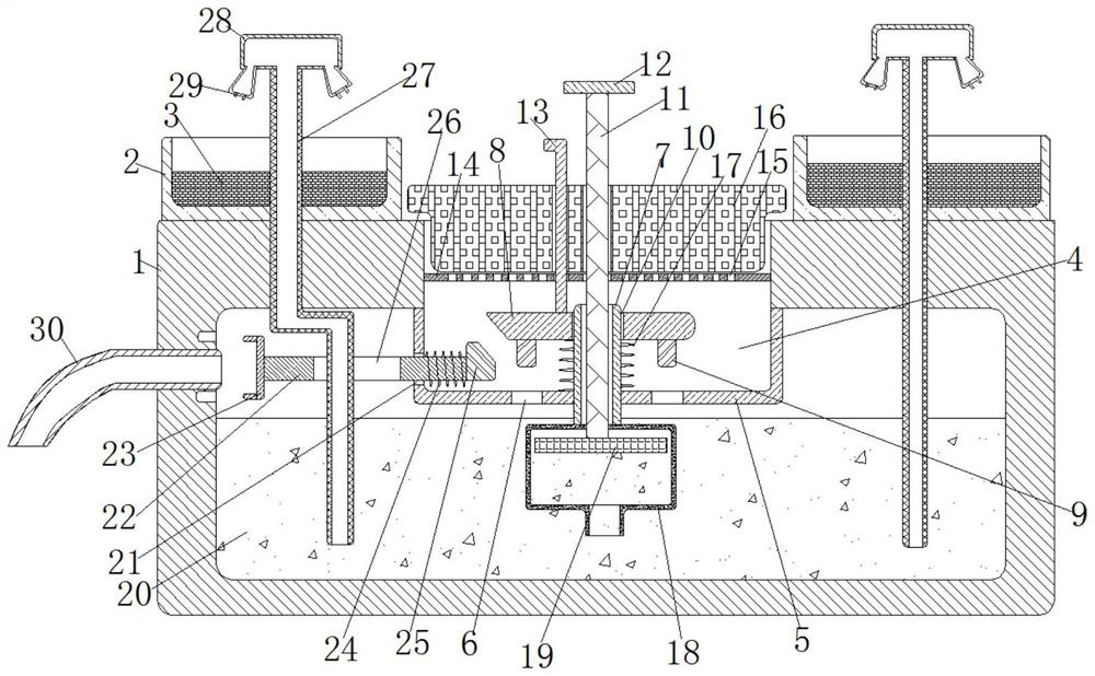
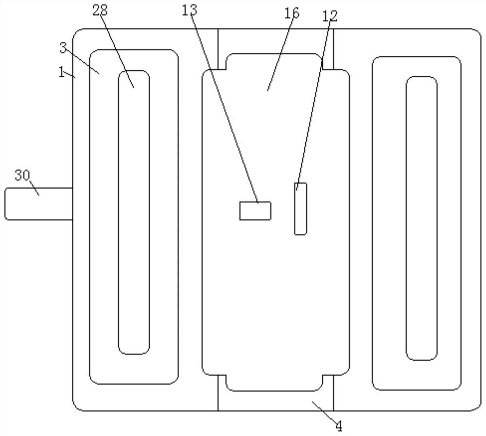
[0025] see Figure 1-4 , a drainage device for a multi-layer environment-friendly permeable floor, comprising a surface 1, the left end of the surface 1 is fixedly plugged with a drainage outlet 30, the drainage outlet 30 is in the shape of an arc, and is convenient for discharging excess rainwater 20 inside the surface 1, and the surface 1 The upper end is fixedly connected to the left with the planting frame 2, the interior of the planting frame 2 is filled ...


PUM


Abstract

The invention relates to the technical field of floor drainage, and discloses a drainage device for a multi-layer environment-friendly permeable floor, including a ground surface, the upper end of the ground surface is fixedly connected with a planting frame to the left, the inside of the planting frame is filled with soil, and the upper end of the ground surface A rectangular groove is provided, a baffle plate is fixedly connected to the upper end inside the ground surface, a square hole is arranged at the lower end of the baffle plate, a fixed cylinder is fixedly inserted in the middle of the upper end of the baffle plate, and a pressure plate is movably socketed on the outside of the fixed cylinder. After each rain, the rainwater flows through the floor layer to the upper end of the filter layer. The rainwater is filtered under the action of the filter layer and then flows to the upper end of the baffle through the leak hole, and then the rainwater flows to the interior of the ground through the square hole for storage. The height of the rainwater inside the surface reaches the opening at the right end of the drain. At this time, the excess rainwater inside the surface is discharged through the drain, so as to effectively absorb road rainwater, effectively replenish groundwater, maintain the balance of the urban natural water system, and reduce the risk of urban waterlogging. Effect.

Description

technical field [0001] The invention relates to the technical field of floor drainage, in particular to a drainage device for multi-layer environment-friendly permeable floors. Background technique [0002] As a new environmentally friendly and ecological road material, permeable floor has attracted increasing attention from people, especially the industry. The surface of modern cities is mostly covered by reinforced concrete buildings and impermeable roads, which are in harmony with natural soil. Compared with ordinary concrete pavement, which lacks the ability to breathe, absorb heat and infiltrate rainwater, it brings a series of environmental problems, and concrete has always been considered the culprit of destroying nature, but as long as continuous voids can be formed, it can Create a connection point with the natural environment. [0003] The existing permeable floor drainage equipment does not have the function of storing water. Whenever it rains, because the permea...

Claims


Application Information

Patent Timeline
Patent Type & Authority Patents(China)
IPC IPC(8): E03F1/00E03F5/10E03F5/14A01G25/02
CPCA01G25/023E03F1/00E03F5/10E03F5/103E03F5/106E03F5/14
Inventor 杨永国
Owner 上海民航新时代机场设计研究院有限公司
Learn More