Oscillating sliding vane jet flow stroke-increasing hydraulic oscillator

A hydraulic oscillator and jet technology, which is used in vibration drilling, vibration generating devices, wellbore/well components, etc., can solve the problems of short service life, many rotating parts, complex structure, etc., and achieve long service life and moving parts. The effect of less and high output efficiency

Active Publication Date: 2020-12-22
SINOPEC OILFIELD EQUIP CORP +1
View PDF7 Cites 1 Cited by
  • Summary
  • Abstract
  • Description
  • Claims
  • Application Information

AI Technical Summary

Problems solved by technology

The problem is that the pressure loss of this solution is high, usually reaching 3~4 Mpa, and the service life is usually less than 500 hours, and the price of the screw motor is very high, such as the structure in Chinese patent document CN205778542U
2. The jet structure uses the vortex cavity to generate vibration and the periodic change of the pressure medium to generate high-frequency vibration, but the pressure loss of this scheme is only 0.2-0.3 Mpa, the frequency is high, and the frequency cannot be controlled
The problem with this solution is that the structure is relatively complex, there are too many rotating parts, the cost is high, the loss is high, and the turbine rotor rotates at a high speed, which makes the output frequency of the tool high, difficult to control, and has a short service life.

Method used


Image

  • Oscillating sliding vane jet flow stroke-increasing hydraulic oscillator
  • Oscillating sliding vane jet flow stroke-increasing hydraulic oscillator
  • Oscillating sliding vane jet flow stroke-increasing hydraulic oscillator

Examples


Embodiment 1

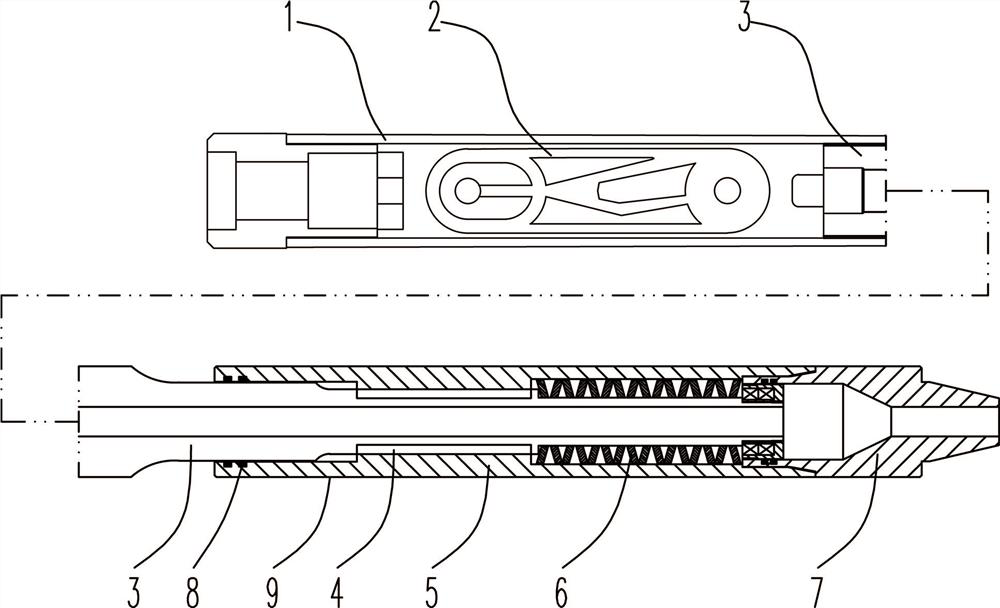
[0033] Such as Figure 1~6 Among them, an oscillating vane jet flow extended range hydraulic oscillator, the outer sleeve 1 is fixed with a vortex cavity body 2, the vortex cavity body 2 is used to generate vibration, and an inlet hole 202 is provided at one end of the vortex cavity body 2. The other end of the vortex cavity body 2 is provided with an outlet hole 203, the outlet hole 203 is located at the center of the vortex cavity 205, and a chute 21 is provided at the inlet end of the inlet hole 202 or at the inlet end of the outlet hole 203, and the sliding The block 22 is slidably installed in the chute 21. One end of the stroke of the moving slider 22 partially covers the inlet hole 202 or the outlet hole 203, and the other end of the stroke completely leaves or the outlet hole 203 to alternately limit the inlet flow. The flow cross section of the hole 202;

[0034] Leaf springs 23 are arranged on both sides of the chute 21 , and the leaf springs 23 are connected with t...

Embodiment 2

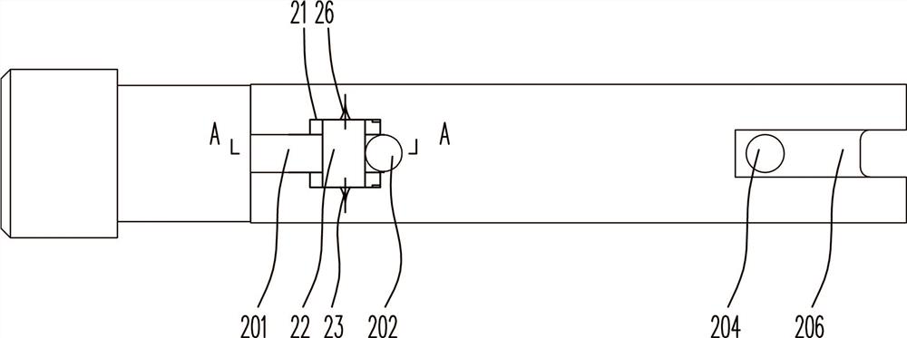
[0037] On the basis of Example 1, the preferred scheme is as Figure 2~3 In the vortex cavity, both sides of the back side of the vortex body 2 are provided with an inlet channel 201, the inlet channel 201 communicates with the inlet hole 202, and the chute 21 is arranged at the position where the inlet channel 201 and the inlet hole 202 are connected, and the chute 21 The bottom surface of the movable slider 22 is lower than the bottom surface of the inlet channel 201, and the top surface of the movable slider 22 is flush with the bottom surface of the inlet channel 201. With this structure, the disturbance to the pressure medium is reduced.

[0038] The preferred solution is as figure 2 Among them, the chute 21 widens to both sides, and the width of the chute 21 and the movable slider 22 is greater than the width of the inlet channel 201;

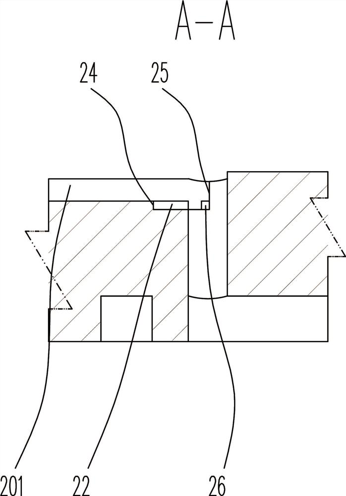
[0039] The two end surfaces of the chute 21 form a first collision surface 24 and a second collision surface 25 for colliding with th...

Embodiment 3

[0041] On the basis of Examples 1 and 2, different from Example 2, the preferred scheme is as Figure 4~6Among them, the chute 21 is lower than the bottom surface of the vortex cavity 205 , and the upper surface of the movable slider 22 is flush with the bottom surface of the volute cavity 205 . With this structure, the movable slider 22 is arranged at the position of the volute cavity 205, which is convenient for arrangement and processing. The upper surface of the movable slider 22 is flush with the bottom surface of the scroll chamber 205 . Disturbances of the pressure medium, in particular vortex-forming pressure medium, are then reduced.

[0042] The preferred solution is as Figure 4~6 Among them, the width of the chute 21 is greater than the diameter of the outlet hole 203, the step between the chute 21 and the outlet hole 203 constitutes the second impact surface 25, and the step at the end of the chute 21 away from the outlet hole 203 constitutes the first impact su...


PUM


Abstract

The invention provides an oscillating sliding vane jet flow stroke-increasing hydraulic oscillator. A vortex cavity is fixedly arranged in an outer sleeve and used for generating vibration; a flow inlet hole is formed in one end of the vortex cavity, and a flow outlet hole is formed in the other end of the vortex cavity and located in the circle center of the vortex cavity; a sliding groove is formed in the inlet end of the flow inlet hole or the inlet end of the flow outlet hole; a movable sliding block is installed in the sliding groove in a sliding manner; one end of the stroke of the movable sliding block partially covers the flow inlet hole or the flow outlet hole, and the other end of the stroke of the movable sliding block completely leaves the flow inlet hole or the flow outlet hole so as to alternately limit the through-flow section of the flow inlet hole; and leaf springs are arranged on the two sides of the sliding groove and connected with the movable sliding block. By theadoption of the scheme that the movable sliding block is arranged in a flow inlet channel or the vortex cavity, the movable sliding block reciprocates through vibration of the vortex cavity, and therefore the through-flow area of the flow inlet channel or a flow outlet channel is changed, the vibration amplitude of the vortex cavity is increased, the vibration frequency is reduced, and then the vibration form meeting the underground construction requirement is obtained, namely the proper amplitude and vibration frequency are obtained.

Description

technical field [0001] The invention relates to the field of oil drilling and production equipment, in particular to an oscillating vane jet flow-extending hydraulic oscillator. Background technique [0002] At present, drilling in oil fields has developed from vertical wells to directional wells and horizontal wells. Drilling tools are usually close to the lower side well wall. The friction of drilling tools on the well wall is too large, which affects the drilling efficiency and makes it difficult to transmit the drilling pressure to the drill bit. In order to overcome this defect, a solution of a hydraulic oscillator has appeared in the prior art, through which the static friction of the drilling tool is changed into dynamic friction to reduce friction. Existing hydraulic oscillators generally have three structures. 1. Screw motor structure, which drives the rotor to rotate through the screw, so that the flow section of the hole between the rotor and the static plate chan...

Claims


Application Information

Patent Timeline
Patent Type & Authority Applications(China)
IPC IPC(8): E21B7/24E21B28/00
CPCE21B7/24E21B28/00
Inventor 钱伟强余长柏宋满华钱德松李文权卢显圣邓福成
Owner SINOPEC OILFIELD EQUIP CORP
Why Eureka
Try Eureka