Belt weigher calibration device

A technology of a calibration device and a belt scale, applied in the field of mechanical structure, can solve the problems that the belt scale cannot achieve physical calibration, the size of the simulation calibration error is difficult, the data and the theoretical value are very different, etc., and the overall structure design is compact and ingenious, and speed tracking is achieved. Accurate and easy to promote the application effect

Inactive Publication Date: 2020-12-22
SHANGHAI MEISHAN IRON & STEEL CO LTD
View PDF7 Cites 3 Cited by
  • Summary
  • Abstract
  • Description
  • Claims
  • Application Information

AI Technical Summary

Problems solved by technology

In the simulation process, there are many interference factors that cannot or are difficult to eliminate. Therefore, in actual work, it can be found that the data obtained by the same belt scale with different calibration methods is very different from the theoretical value, and the difference between different scales is not the same. It brings great difficulty for us to judge the possible error size of analog calibration
Due to the lack of on-site conditions or insufficient maintenance personnel, most belt scales cannot achieve physical calibration, so a better calibration method is needed to replace physical calibration and achieve higher calibration accuracy

Method used


Image

  • Belt weigher calibration device
  • Belt weigher calibration device

Examples


Embodiment 1

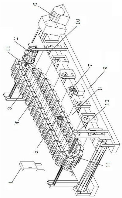
[0019] Embodiment 1: see figure 1 , a kind of belt scale calibration device, said calibration device includes instrument box 1, speed-regulating motor 2, chain code 3, chain code drive chain 4 and high-speed camera 5, calibration device supporting frame 10, said chain code 3 and high-speed camera 5 is fixed on the chain code driving chain 4, and the calibration device is arranged on the calibration device support frame. The calibration device is set on the belt scale, and the calibration device and the belt scale are installed on the conveyor belt conveyor support. The head and tail of the calibration device are respectively provided with rollers 11, and the roller shafts of the head are in line with the adjustment The shaft of the high-speed motor is connected, and the number of the high-speed cameras is 2-4, which are evenly arranged on the chain 4 driven by the chain code. Chain sign indicating number drives chain 4 and adopts rubber bearing, and the surface is the concave...

Embodiment 2

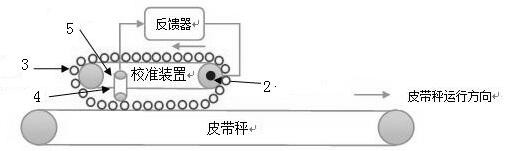
[0022] Embodiment 2: the calibration method of the belt scale calibration device, the method is as follows: the chain code is sleeved on a section of cyclically revolving drive chain, the drive chain is driven by a speed-regulating electric drive, the high-speed camera is installed on the drive chain, and the high-speed camera collects The information is transmitted to the feedback device, and the feedback device outputs the control current to the speed-regulating motor. Such as figure 2 , the lower half circle of the driving chain is in the same direction as the running direction of the belt scale belt. The camera installed on the driving chain can only play a tracking role when the driving chain turns to the lower half circle. Therefore, in order to improve the tracking effect, it is recommended to evenly Arrange 2 to 3 cameras in an orderly manner. The cameras work in rotation to ensure that the calibration device can track the belt speed at all times. After the belt sca...


PUM


Abstract

The invention relates to a belt weigher calibration device, which is characterized in that the calibration device comprises an instrument box, a speed regulation motor, a chain weight, a chain weightdriving chain, a high-speed camera and a calibration device support frame, the chain weight and the high-speed camera are fixed on the chain weight driving chain, and a calibration device body is arranged on the calibration device support frame. According to the scheme, due to the fact that the speeds are completely consistent, a weight counting sensor does not need to calculate the weight difference value caused by the speed difference, the weight added to a belt weigher is always a section of uniform chain weight, a speed measuring sensor is not needed on the driving chain, the driving chaintracks the belt speed of the belt weigher in an optical mode, and accuracy and reliability are achieved.

Description

technical field [0001] The invention relates to a calibration device, in particular to a belt scale calibration device, which belongs to the technical field of mechanical structures. Background technique [0002] Currently, the main form of belt scales is electronic belt scales. The best calibration method is physical calibration. The national verification regulations also regard physical calibration as the only approved calibration method, and other calibration methods can only be used as supplements. Other calibration methods can be collectively referred to as analog calibration, such as hanging code calibration, chain code calibration, electronic calibration, etc. They all use a known physical quantity to simulate the physical quantity generated by the physical ballast belt scale for calibration. The standard value of the test is the theoretical value calculated by the formula. In the simulation process, there are many interference factors that cannot or are difficult to...

Claims


Application Information

Patent Timeline
Patent Type & Authority Applications(China)
IPC IPC(8): G01G23/01
CPCG01G23/01
Inventor 刘伟孙继芳
Owner SHANGHAI MEISHAN IRON & STEEL CO LTD
Why Eureka
Try Eureka