
Complex wiring harness tool plate design system

A design system and tooling drawing technology, applied in computer-aided design, calculation, instruments, etc., can solve the problems of high design intensity, error-prone, low efficiency, etc., to ensure the accuracy of wiring, improve efficiency, save manpower and material technology cost effect

Active Publication Date: 2020-12-22
CHANGCHUN UNIV OF SCI & TECH +2
View PDF10 Cites 0 Cited by
  • Summary
  • Abstract
  • Description
  • Claims
  • Application Information

AI Technical Summary

Problems solved by technology

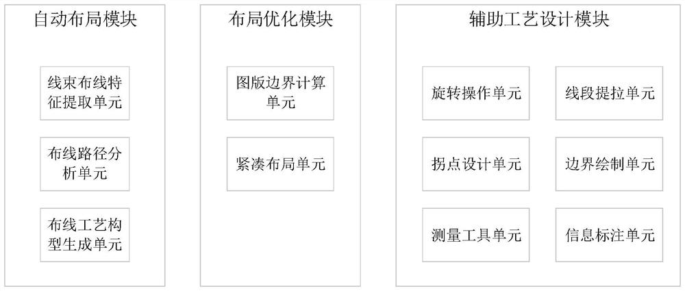
[0006] In order to solve the problems that the process design of complex wire harnesses in the prior art needs to be completed manually by technicians, the configuration design and dimensional accuracy of wire harnesses are difficult to control, the design strength is high, the efficiency is low, and error-prone, etc., the present invention provides a tooling plate design system for complex wire harnesses. It can automatically complete the process design of complex wiring harnesses, perform wiring process configuration layout, and optimize the configuration according to the boundary size requirements of the process layout. It also provides auxiliary process design modules for designers to choose. The generated wiring harness tooling drawings can be directly provided to The operator completes the wiring work, improves efficiency, and can ensure the accuracy of wiring harnesses with complex configurations, saving a lot of manpower and material technology costs for aircraft, ship and other research and development units and production companies, and has a huge market application prospect

Method used


Image

  • Complex wiring harness tool plate design system
  • Complex wiring harness tool plate design system
  • Complex wiring harness tool plate design system

Examples


Embodiment Construction

[0044] Below in conjunction with accompanying drawing and embodiment further illustrate technical scheme of the present invention:

[0045] A tooling design system for complex wire harnesses, including:

[0046] Automatic layout module: analyze the data in the circuit schematic diagram and the wire table, extract the characteristic elements of the wiring harness wiring, arrange the wiring harness wiring path, and perform the layout of the wiring process configuration;

[0047] Layout optimization module: according to the boundary size requirements of the process layout, optimize the layout of the wiring process configuration completed by the automatic layout module, so that the optimized wiring harness layout meets the engineering wiring requirements, and obtain the wiring harness tooling layout;

[0048] Auxiliary process design module: Provides a common drawing function module for wiring tooling layout design, which is used for designers to modify the wiring process layout o...


PUM


Abstract

The invention discloses a complex wiring harness tool plate design system which comprises the components of an automatic layout module which analyzes data in a circuit schematic diagram and a wire table, extracts wiring harness wiring characteristic elements, arranges wiring harness wiring paths and performs wiring process configuration layout; a layout optimization module, used for carrying out configuration optimization on the wiring process configuration layout completed by the automatic layout module according to the process layout boundary dimension requirement, so that the optimized wiring harness wiring layout meets the engineering wiring requirement, and a wiring harness tool plate is obtained; and an auxiliary process design module, providing a common drawing function module for wiring tool plate design, and used for a designer to modify the wiring process layout obtained by the automatic layout module or the layout optimization module or draw a wiring process plate by himself / herself. According to the invention, process design of complex wiring harnesses can be automatically completed, wiring process configuration layout is carried out, configuration optimization is carried out according to process layout boundary dimension requirements, and an auxiliary process design module is provided for designers to select.

Description

technical field [0001] The invention relates to a wiring process design system, in particular to a complex wiring harness tooling plate design system, which belongs to the technical field of large-scale equipment wiring harness wiring. Background technique [0002] Wire harnesses are an indispensable and important part of many products, equipment, and equipment, such as aircraft, ships, automobiles, and rail cars. Wire harness generally goes through three main stages from design to finished product: principle design, process design and product production. Through the principle design stage, the circuit principle design of the wiring harness is completed and the wire table is generated; through the process design stage, the tooling plate for process production is drawn according to the circuit schematic diagram and the wire table; finally, the wire harness wiring is completed according to the tooling plate in the product production stage. [0003] The wiring process of the w...

Claims


Application Information

Patent Timeline
Patent Type & Authority Applications(China)
IPC IPC(8): G06F30/394G06F30/392
CPCG06F30/394G06F30/392
Inventor 田春林穆志国胡青范军华李林刘贡平马国庆黄慧萍程佳敏贾冰张桂林高艺乔晓利
Owner CHANGCHUN UNIV OF SCI & TECH
Learn More