Current mode controlled BOOST converter

A current mode and converter technology, which is applied in the direction of output power conversion device, control/regulation system, DC power input conversion to DC power output, etc. It can solve the problem of large duty cycle sub-harmonic oscillation, difficult loop control, Issues such as narrow input range, to achieve wide input voltage, easy loop stability, and avoid sub-harmonic oscillation

Pending Publication Date: 2020-12-22
SUZHOU KAIWEITE SEMICON
View PDF0 Cites 2 Cited by
  • Summary
  • Abstract
  • Description
  • Claims
  • Application Information

AI Technical Summary

Problems solved by technology

However, in the design of BOOST boost system, there are often problems such as large output ripple, n...

Method used


Image

  • Current mode controlled BOOST converter
  • Current mode controlled BOOST converter
  • Current mode controlled BOOST converter

Examples


Embodiment 1

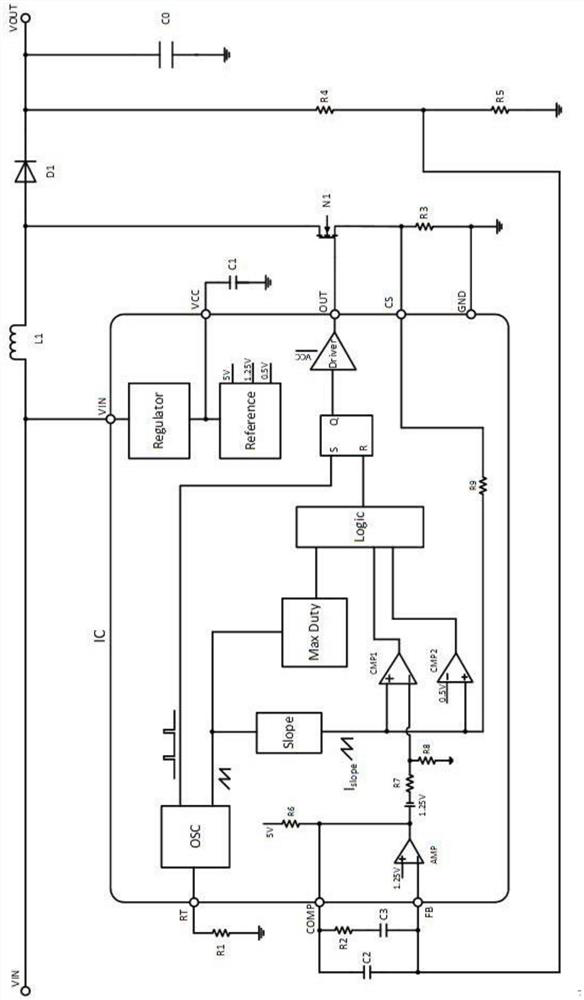
[0015] Embodiment 1: see figure 1 , a current mode controlled BOOST converter provided by the present invention, such as figure 1As shown, the whole system includes the control IC and peripheral circuits. IC peripheral components: VIN is the input voltage of the system; VOUT is the output voltage of the system; L1 is the inductor; D1 is the freewheeling diode; C0 is the output filter capacitor; N1 power switch tube; A resistor, connected to the RT pin of the IC, is used to control the operating frequency of the system; R2, C2, and C3 are the FB pin and COMP pin compensation network of the IC, which play a decisive role in the stability of the system; R3 is the current sampling resistor; R4 , R5 constitutes the sampling network of the output voltage, and its ratio determines the level of the output voltage. There are several core modules inside the IC: Regulator module, OSC is the oscillator module, Slope is the slope compensation module, MaxDuty is the maximum duty cycle mod...


PUM


Abstract

The invention relates to a current mode controlled BOOST converter, and the converter comprises a control IC and a peripheral circuit, wherein the IC peripheral circuit comprises VIN which is an inputvoltage of a system; VOUT which is the output voltage of the system; L1 which is an inductor; D1 which is a fly-wheel diode; C0 which is an output filter capacitor; an N1 power switch tube; C1 whichis a VCC pin plug-in capacitor of the IC; R1 which is a resistor, is connected with an RT pin of the IC and is used for controlling the working frequency of the system; R2, C2 and C3 which are FB pinand COMP pin compensation networks of the IC and play a role in deciding the stability of the system; R3 which is a current sampling resistor; R4 and R5 which form a sampling network of the output voltage, wherein the proportion of R4 and R5 determines the magnitude of the output voltage. The current mode BOOST converter provided by the scheme has wide input voltage, output ripples are easy to reduce, subharmonic oscillation is eliminated, and loop stability is convenient to adjust.

Description

technical field [0001] The invention relates to a converter, in particular to a BOOST converter controlled by a current mode, and belongs to the technical field of power management. Background technique [0002] BOOST boost circuit is a switching DC boost circuit that can make the output voltage higher than the input voltage. Widely used in DC motor drives, single-phase power factor correction (PFC) circuits and other AC and DC power supplies. However, in the design of the BOOST boost system, there are often problems such as large output ripple, narrow input range, sub-harmonic oscillation and difficult loop control when working with a large duty cycle. Therefore, there is an urgent need for a new solution to solve the above technical problems. Contents of the invention [0003] The present invention aims at the problems existing in the prior art, and provides a current mode controlled BOOST converter. The technical solution is a current mode controlled BOOST converter, ...

Claims


Application Information

Patent Timeline
IPC IPC(8): H02M3/156H02M1/08
CPCH02M1/08H02M3/156H02M1/0003
Inventor 涂才根张胜谭在超罗寅丁国华
Owner SUZHOU KAIWEITE SEMICON
Why Eureka
Try Eureka