
Hardware part machining die with discharging mechanism

A discharging mechanism and mold processing technology, which is applied in the field of hardware processing, can solve the problems of lack of mold release means and complexity of molds, and achieve the effects of shortening cooling time, reducing the difficulty of discharging, and improving the efficiency of discharging

Pending Publication Date: 2020-12-25
河北冰虫环保科技有限公司
View PDF8 Cites 5 Cited by
  • Summary
  • Abstract
  • Description
  • Claims
  • Application Information

AI Technical Summary

Problems solved by technology

[0004] The purpose of the present invention is: in order to solve the change of the size and model of the hardware to be processed, it is more complicated to replace and adjust the mold base, and the mold lacks effective demoulding means after the hardware is processed, and manual demoulding is required. problem, and proposed a metal parts processing mold with a discharge mechanism

Method used


Image

  • Hardware part machining die with discharging mechanism
  • Hardware part machining die with discharging mechanism
  • Hardware part machining die with discharging mechanism

Examples


Embodiment approach

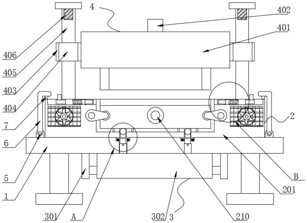
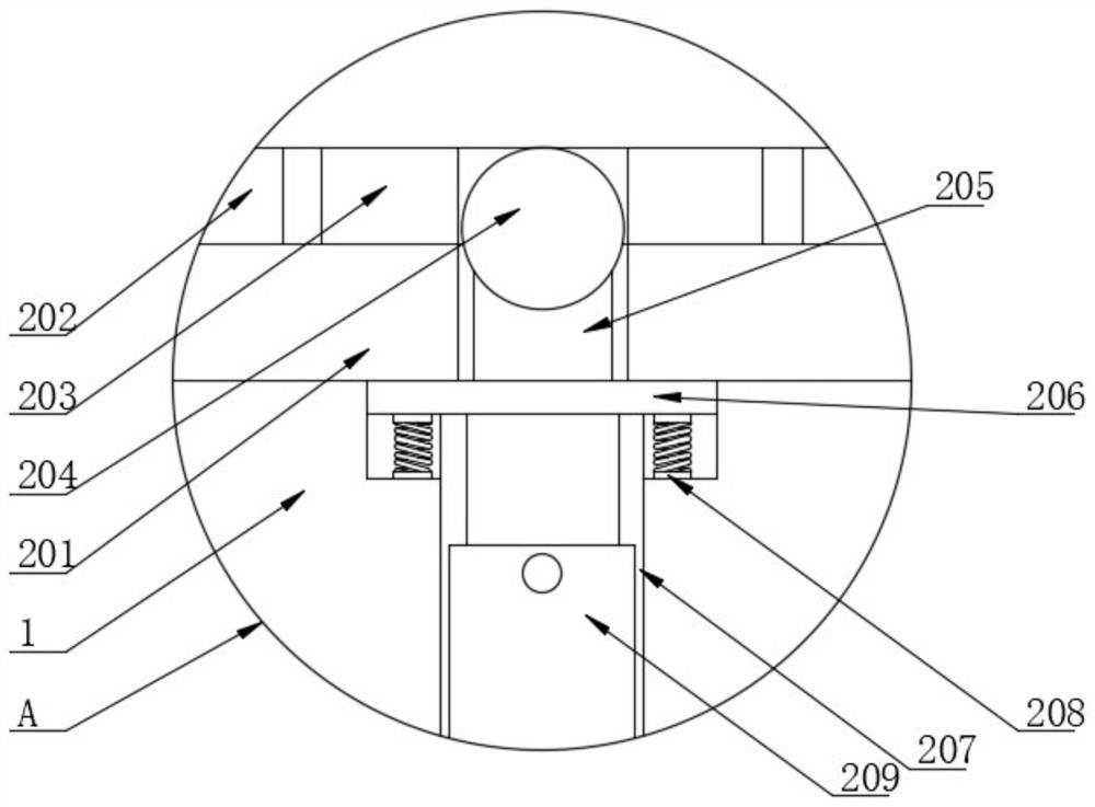
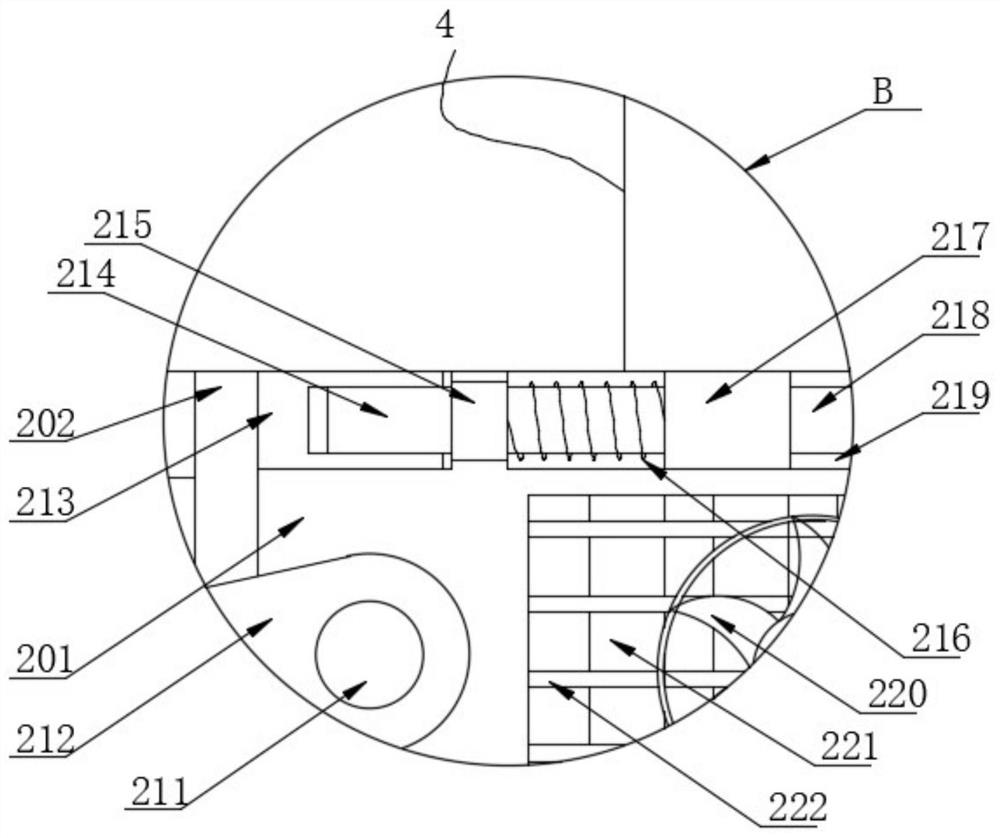
[0046] The implementation method is as follows: After the lower mold base 202 is snapped into the fixed base 201, the stamping hardware is placed on the top of the fixed base 201, and the upper transmission rod 402 drives the upper mold base 401 and the second sliding sleeves 404 on both sides on the second sliding rod. 405 slides outside, and the upper mold base 401 moves downward to contact the stamping hardware with the lower mold base 202. After the stamping contacts, the object is stamped and limited in the lower mold base 202 of the limit seat, and passes through by twisting the limit plates 212 on both sides. The pin shaft 211 is separated from the lower mold base 202, and the limit plate 212 can limit and support the lower mold base 202 during stamping, avoid shaking, improve overall safety, and control the external oil circuit switch to control the hydraulic cylinders 209 on both sides of the bottom. The hydraulic rod is extended, and the hydraulic rod of the hydraulic...


PUM


Abstract

The invention discloses a hardware part machining die with a discharging mechanism, and belongs to the technical field of hardware part machining. The hardware part machining die comprises a base, wherein a lower die mechanism is arranged at the top of the base; an upper die mechanism is fixedly connected to the top of the lower die mechanism; a supporting mechanism is arranged on one side of thebase; the supporting mechanism is located on one side of a lower die base; the lower die mechanism comprises a fixing base; the lower die base is movably connected to an inner cavity of the fixing base; first sealing rings are embedded in the two sides of the bottom of an inner cavity of the lower die base; a second sealing ring is embedded in one side of the inner cavity of the lower die base; and convex blocks are in sliding connection to inner cavities of the first sealing rings and the second sealing ring. According to the hardware part machining die, after the lower die base is clamped into the fixing base, a stamping part can be stored and placed on a containing plate, after multiple times of stamping is completed, collecting, transferring and moving are carried out, thus dischargingand placing of the stamped stamping part are remarkably improved, the discharging difficulty after stamping is reduced, work of workers is remarkably facilitated, and the overall use requirement is met.

Description

technical field [0001] The invention belongs to the technical field of hardware processing, and in particular relates to a processing mold for hardware parts with a discharging mechanism. Background technique [0002] Hardware refers to mechanical parts or parts for assembly that are processed and cast by traditional metals. Hardware can be used alone or as auxiliary tools, such as hardware tools and hardware parts. Most of the small hardware products are not final consumer goods. Most of the processing is done by die-casting or stamping, and stamping generally requires the use of processing molds. The precision of the molds is an important guarantee for the overall strength of the hardware. [0003] Most of the hardware molds in the prior art can only process a single hardware part. When the size and model of the hardware to be processed changes, it is more complicated to replace and adjust the mold base, and the mold lacks an effective tool after the hardware is processed....

Claims


Application Information

Patent Timeline
Patent Type & Authority Applications(China)
IPC IPC(8): B21D45/04B21D37/10B21D37/04B21D37/16B21D22/02
CPCB21D45/04B21D37/10B21D37/04B21D37/16B21D22/02
Inventor 朱玲玲
Owner 河北冰虫环保科技有限公司
Learn More