Supercharge Your Innovation With Domain-Expert AI Agents!

Double-row leather collar yarn guide assembly of ring spinning frame and ring spinning frame

A spinning frame and apron technology, applied in the field of spinning, can solve problems such as the influence of installation error and transmission deviation on spinning index, increased difficulty of installation and replacement, and complex structure

Pending Publication Date: 2020-12-25
李岚
View PDF3 Cites 1 Cited by
  • Summary
  • Abstract
  • Description
  • Claims
  • Application Information

AI Technical Summary

Problems solved by technology

[0002] Both patents ZL201480019063.X and ZL201710327732.5 disclose a type of yarn-drawing assembly with double row aprons. In the assembly, the two lower aprons arranged side by side are fitted on the bottom rollers. To replace and install the lower aprons, the bottom rollers need to be disassembled. , in the double-row apron threading assembly, the circumference of the two lower aprons juxtaposed on the same spindle position is different, and the rollers of the snare are different. The long lower apron needs to be covered by two lower rollers. It is more difficult to install and replace the lower apron in the row apron yarn-drawing assembly. For this reason, the patent CN201822092749. Combination of supporting parts, for the two adjacent spindle positions, use detachable supporting parts to hold the apron rollers of the two spindle positions, the lower roller drives the apron roller, and then drives the upper roller, although the disassembly of the lower apron is convenient , but the structure is very complicated. The middle roller and the rear roller frictionally drive the apron roller, and then indirectly drive the top roller. The installation error and transmission deviation between the spindles will affect the spinning index

Method used


Image

  • Double-row leather collar yarn guide assembly of ring spinning frame and ring spinning frame
  • Double-row leather collar yarn guide assembly of ring spinning frame and ring spinning frame

Examples


Embodiment 1

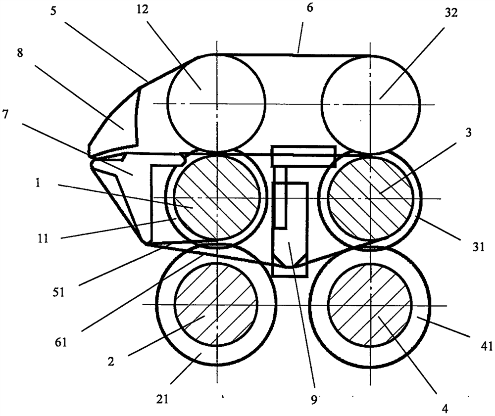
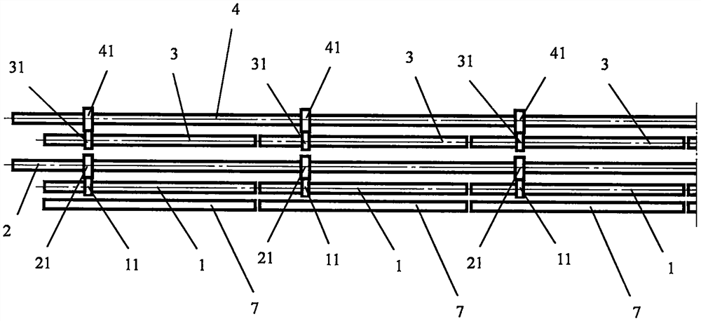
[0018] Such as figure 1 As shown, the cross-sectional schematic diagram of the double-row apron yarn delivery assembly of the ring spinning machine, the assembly includes a middle roller 1, a middle top roller 12, a middle roller transmission shaft 2, a middle roller transmission gear 21, a rear roller 3, Rear upper roller 32, rear roller transmission shaft 4, rear roller transmission gear 41, middle upper apron 5, middle lower apron 51, rear upper apron 6, rear lower apron 61, lower shaft 7, upper shaft 8, rear lower apron Ring tension frame 9, middle upper apron 5 is set on middle upper roller 12 and upper roller 8, middle and lower apron 51 is set on lower roller 7 and middle roller 1, rear upper apron 6 spans middle upper roller 12 and is set on rear upper Roller 32 and upper roller 8, and rear lower apron 61 straddle middle roller 1 and set on lower roller 7 and rear roller 3, and are tightened by the action of lower apron tension frame 9, and the middle upper apron 5 and...


PUM


Abstract

The invention discloses a double-row leather collar yarn guide assembly of a ring spinning frame. The number of middle roller sections and the number of rear roller sections are equal to the number oflower pins; the middle roller sections, the rear roller sections and the lower pins are distributed in a front-back correspondence manner according to the ratio of 1: 1: 1; the two adjacent middle roller sections are not directly connected; the two adjacent rear roller sections are also not directly connected; each middle roller section and each rear roller section can be detached; a middle roller and a rear roller which are adjacent to each other are not changed and moved; each middle roller section is driven by a middle roller transmission shaft; each rear roller section is driven by a rearroller transmission shaft; and a transmission path of each machine part of the yarn guide assembly is that the middle roller transmission shaft drives each middle roller section through a middle roller transmission gear, the middle roller drives a middle-upper roller and drives a middle-upper leather collar and a middle-lower leather collar to move at the same time, the rear roller transmission shaft drives each rear roller section through a rear roller transmission gear, and the rear roller drives a rear-upper roller and drives a rear-upper leather collar and a rear-lower leather collar to move at the same time.

Description

technical field [0001] The invention belongs to the technical field of spinning, and relates to a double row apron yarn drawing assembly of a ring spinning frame and the ring spinning frame. Background technique [0002] Both patents ZL201480019063.X and ZL201710327732.5 disclose a type of yarn-drawing assembly with double row aprons. In the assembly, the two lower aprons arranged side by side are fitted on the bottom rollers. To replace and install the lower aprons, the bottom rollers need to be disassembled. , in the double-row apron threading assembly, the circumference of the two lower aprons juxtaposed on the same spindle position is different, and the rollers of the snare are different. The long lower apron needs to be covered by two lower rollers. It is more difficult to install and replace the lower apron in the row apron yarn-drawing assembly. For this reason, the patent CN201822092749. Combination of supporting parts, for the two adjacent spindle positions, use de...

Claims


Application Information

Patent Timeline
Patent Type & Authority Applications(China)
IPC IPC(8): D01H5/26D01H1/22
CPCD01H1/22D01H5/26
Inventor 陈伟雄
Owner 李岚
Features
  • R&D
  • Intellectual Property
  • Life Sciences
  • Materials
  • Tech Scout
  • Unparalleled Data Quality
  • Higher Quality Content
  • 60% Fewer Hallucinations
Learn More