Externally-adhered reinforced glass beam and manufacturing method thereof
A reinforced, glass technology, applied in the direction of joists, girders, trusses, etc., can solve the problems of reduced bearing capacity, failure brittleness, etc., achieve high compressive strength, improve bearing capacity and deformation capacity, and improve the bearing capacity after cracking and deformability effects
- Summary
- Abstract
- Description
- Claims
- Application Information
AI Technical Summary
Problems solved by technology
Method used
Image
Examples
Embodiment 1
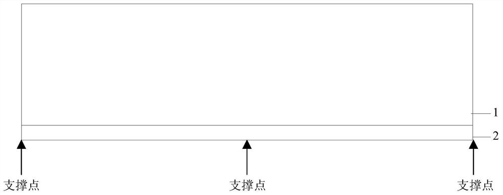
[0035] Glass beam 1 is laminated glass composed of a middle layer of glass and two layers of glass on the outside. The glass material is flat glass. The cross-section of glass beam 1 is configured as 6mm+1.52SGP+12mm+1.52SGP+6mm; The section of reinforcement 2 is U-shaped, and the inner width of the U-shaped groove of reinforcement 2 is 4mm larger than the width of the glass beam, and the height of U-shaped groove is 1 / 2 of its inner width; at the two ends of reinforcement 2 and the span Set three supports at the middle position, and set acrylic foam tape between the reinforcement 2 and the glass beam 1 at the support as the pad 4. The width of the pad 4 is equal to the inner width of the U-shaped groove of the reinforcement 2, and the length is 20mm. The thickness is 2 mm, and it is pasted on the inner bottom surface of the reinforcement 2; the gap between the bottom and lower part of the glass beam 1 and the reinforcement 2 is an MF1310 adhesive layer 3 with a thickness of 2 ...
Embodiment 2
[0038]Except that the material of reinforcement 2 is GFRP (glass reinforced plastic), the others are the same as in Embodiment 1.
[0039] Carry out four-point bending test to the non-reinforced glass beam, the externally bonded stainless steel reinforced reinforced glass beam prepared in Example 1 and the externally bonded GFRP reinforced reinforced glass beam prepared in Example 2, and the results are as follows Figure 4 As shown, it can be seen from the load-displacement curve obtained in the four-point bending test that compared with the laminated glass beam, the externally bonded stainless steel reinforced reinforced glass beam prepared in Example 1 and the externally bonded GFRP prepared in Example 2 The bearing capacity and deformation capacity of the reinforced glass beam after cracking are significantly improved compared with the laminated glass beam.
Embodiment 3
[0041] Glass beam 1 is laminated glass composed of a middle layer of glass and two outer layers of glass. The glass material is semi-tempered glass. The cross-section configuration of glass beam 1 is 6mm+1.52SGP+12mm+1.52SGP+6mm; reinforcement 2 is stainless steel , the section of reinforcement 2 is U-shaped, the inner width of the U-shaped groove of reinforcement 2 is 4mm larger than the width of the glass beam, and the height of U-shaped groove is 1 / 2 of its inner width; at the two ends of reinforcement 2 and Three supports are set at the mid-span position, and acrylic foam tape is set between the reinforcement 2 and the glass beam 1 at the support as the spacer 4. The width of the spacer 4 is equal to the inner width of the U-shaped groove of the reinforcement 2, and the length is 20mm , with a thickness of 2 mm, pasted on the inner bottom surface of the reinforcement 2; the gap between the bottom and lower part of the glass beam 1 and the reinforcement 2 is an MF1310 adhesi...
PUM
| Property | Measurement | Unit |
|---|---|---|
| thickness | aaaaa | aaaaa |
| length | aaaaa | aaaaa |
| viscosity | aaaaa | aaaaa |
Abstract
Description
Claims
Application Information
 - R&D
- Intellectual Property
- Life Sciences
- Materials
- Tech Scout
- Unparalleled Data Quality
- Higher Quality Content
- 60% Fewer Hallucinations
Browse by: Latest US Patents, China's latest patents, Technical Efficacy Thesaurus, Application Domain, Technology Topic, Popular Technical Reports.
© 2025 PatSnap. All rights reserved.Legal|Privacy policy|Modern Slavery Act Transparency Statement|Sitemap|About US| Contact US: help@patsnap.com


