Femoral neck fracture reduction pressurizer

A femoral neck fracture and pressurizer technology, applied in the field of medical devices, can solve the problems of nonunion of fractures, long healing time for patients, inability to accurately reset and pressurize the fracture ends, and achieve the effect of not easily falling off

Inactive Publication Date: 2020-12-29
北京中安泰华科技有限公司
View PDF0 Cites 2 Cited by
  • Summary
  • Abstract
  • Description
  • Claims
  • Application Information

AI Technical Summary

Problems solved by technology

These methods are all indirect reduction. After reduction, a locking plate is used to firmly fix the fracture, and it is impossible to perform precise reduction and pressure on the broken end of the fracture, resulting in long healing time for patients after surgery, fracture nonunion, and complications such as femoral head necrosis. high probability

Method used


Image

  • Femoral neck fracture reduction pressurizer
  • Femoral neck fracture reduction pressurizer
  • Femoral neck fracture reduction pressurizer

Examples


Embodiment 1

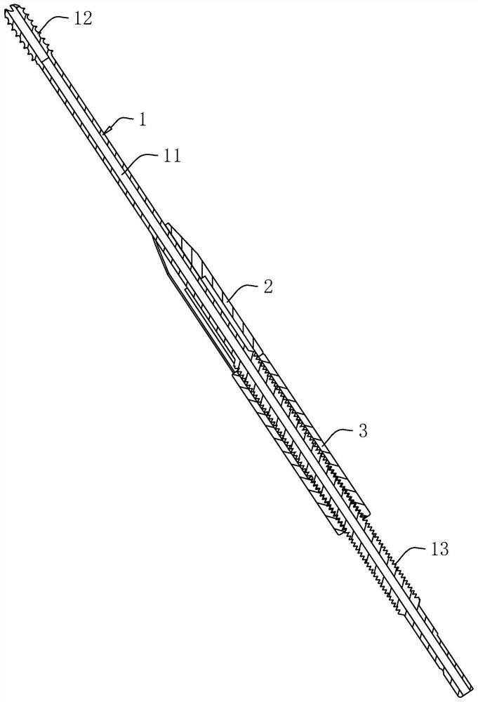
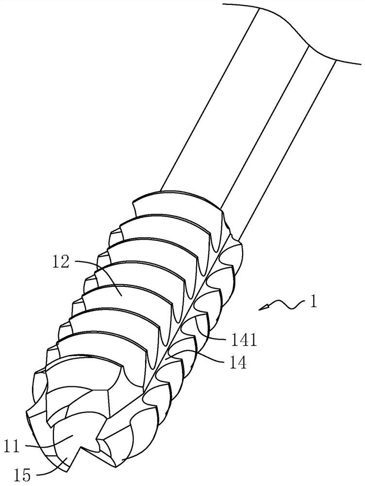
[0040] refer to figure 1 The femoral neck fracture reduction pressurizer includes a reduction tap 1 , and a compression sleeve 2 and a compression nut 3 are sheathed on the reduction tap 1 . The reset tap 1 is in the shape of a long rod, and an axially extending guide through hole 11 is opened inside it. The head of the reset tap 1 is provided with a self-tapping thread 12, and a guide external thread 13 is processed near the tail end. The pressure sleeve 2 Sleeved between the self-tapping thread 12 and the guide external thread 13, the pressure nut 3 is threadedly matched with the guide external thread 13, and both the pressure nut 3 and the pressure sleeve 2 can move axially along the reset tap 1, and the two mutually Adjacent end faces can abut against each other.

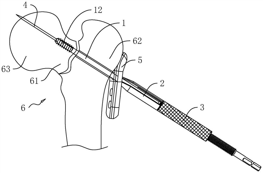
[0041] refer to figure 2 , the use of the femoral neck fracture reduction pressurizer needs to cooperate with the Kirschner wire 4 and the locking plate 5. During the operation, first use the drilling equipme...

Embodiment 2

[0049] refer to Figure 7 , The difference between this embodiment and the embodiment is that a stopper 7 is provided in the installation opening 22 of the pressure sleeve 2 to prevent the pressure sleeve 2 from detaching from the reset tap 1 .

[0050] The limiting member 7 is configured as a U-shaped structure, and the distance between two opposite outer sidewalls of the limiting member 7 is slightly larger than the width of the installation opening 22 . When installing, turn the pressure sleeve 2 so that the flat position 16 faces the installation hole 22, and then put the opening of the limiter 7 toward the installation port 22 and install it, and the opposite sides of the limiter 7 press the two sides of the installation port 22 respectively. inner wall. Both ends of the limiting member 7 are integrally connected with clamping parts 71 , and the two clamping parts 71 are respectively engaged with two inner edges of the installation opening 22 to prevent the limiting memb...


PUM


Abstract

The invention relates to the technical field of medical instruments, in particular to a femoral neck fracture reduction pressurizer. The femoral neck fracture reduction pressurizer comprises a reduction screw tap, a pressurizing sleeve and a pressurizing nut, the reduction screw tap is sleeved with the pressurizing sleeve and the pressurizing nut, self-tapping threads are arranged at a head of thereduction screw tap, guiding external threads are machined at a position, close to a tail end, of the reduction screw tap, the pressurizing sleeve is arranged between the self-tapping thread and theguide external thread of a reset screw tap in a sleeved mode, the pressurizing nut is matched with the guide external thread in a threaded mode, and an end face of the pressurizing sleeve abuts against an end face of the pressurizing nut. The femoral neck fracture reduction device can shorten healing time of a patient after a femoral neck fracture reduction operation and reduce probability of complications.

Description

technical field [0001] The present application relates to the field of medical devices, in particular to a femoral neck fracture reduction press. Background technique [0002] In the field of surgical medicine, the current reduction methods for femoral neck fractures include: traction reduction, closed manipulation reduction (MCEvenny method, Lead better method), percutaneous needle prying reduction. These methods are all indirect reduction. After reduction, a locking plate is used to firmly fix the fracture, and it is impossible to perform precise reduction and pressure on the broken end of the fracture, resulting in long healing time for patients after surgery, fracture nonunion, and complications such as femoral head necrosis. The odds are high. Contents of the invention [0003] In order to speed up the healing time of patients after femoral neck fracture reduction surgery and reduce the chance of complications, the present application provides a femoral neck fracture...

Claims


Application Information

Patent Timeline
IPC IPC(8): A61B17/74A61B17/86A61B17/80A61B17/88
CPCA61B17/746A61B17/8014A61B17/8019A61B17/8057A61B17/8061A61B17/86A61B17/8625A61B17/864A61B17/8685A61B17/8897
Inventor 秦保祯李东贤周中位罗爱民
Owner 北京中安泰华科技有限公司
Why Eureka
Try Eureka