
Mixing system for improving solid-liquid-gas mixing performance

A mixing system, solid-liquid mixing technology, applied in mixers, fluid mixers, dissolution and other directions, can solve the problems of large adjustment mode limitations, limited ejector capacity, and single ejector structure.

Pending Publication Date: 2020-12-29
大庆德美特尔能源科技有限公司
View PDF0 Cites 1 Cited by
  • Summary
  • Abstract
  • Description
  • Claims
  • Application Information

AI Technical Summary

Problems solved by technology

[0004] The structure of the existing ejector is single, it is easy to cause blockage of the powder pipe, the capacity of the ejector is limited, and the general preparation volume is only 60m 3 / h, the preparation concentration is 5000-6000ppm, and the suction distance is only more than 2m
Today, when the chemical expulsion step has become the main means of improving oil recovery, new and higher requirements are constantly put forward for the polymer solution preparation process (higher solution concentration, larger solution preparation volume, more accurate preparation of solution concentration, providing Higher suction lift, etc.); at the same time, in different tertiary oil recovery processes, when configuring polymer solutions with different concentrations, it is necessary to adjust the relative addition of dry powder and water. In the existing polymer dispersion device, it is necessary to control the dry powder and water separately. The amount of water added, and the amount of dry powder added can only be adjusted by adjusting the gas flow rate of the ejector. This adjustment method has relatively large limitations, which is not conducive to the accurate preparation of the concentration of the polymer solution and the polymer solution with a higher concentration.

Method used


Image

  • Mixing system for improving solid-liquid-gas mixing performance
  • Mixing system for improving solid-liquid-gas mixing performance
  • Mixing system for improving solid-liquid-gas mixing performance

Examples


Embodiment Construction

[0034] In order to clearly illustrate the design concept of the present invention, the present invention will be described below in conjunction with examples.

[0035] In order to enable those skilled in the art to better understand the solution of the present invention, the technical solution of the present invention is clearly and completely described below in conjunction with the accompanying drawings in the examples of the present invention. Obviously, the described examples are only part of the examples of the present invention , not all examples. Based on the examples in the present invention, all other implementations obtained by those skilled in the art without making creative efforts shall fall within the protection scope of the present invention.

[0036] In the description of this embodiment, the orientations or positional relationships indicated by the terms "upper", "lower", "left", "right" are all based on the orientations or positional relationships shown in the...


PUM


Abstract

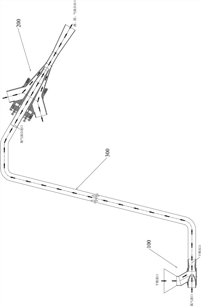
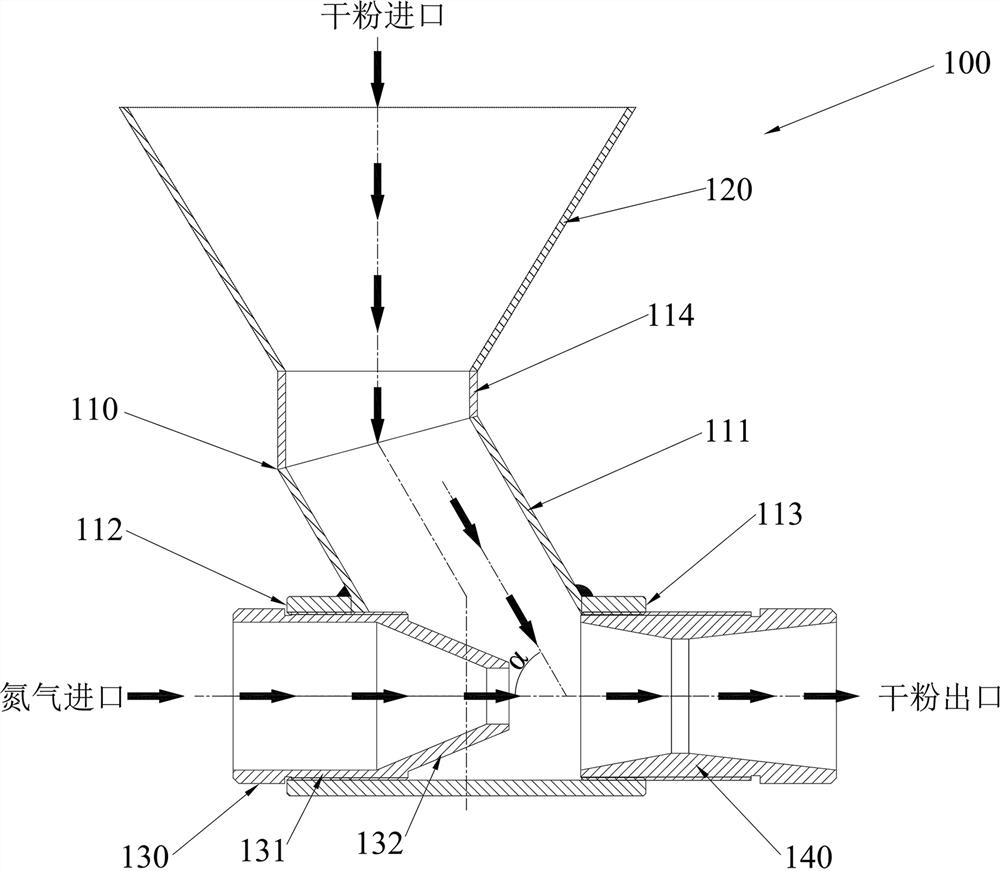
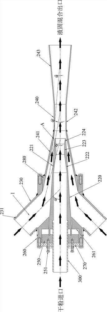
The invention discloses a mixing system for improving solid-liquid-gas mixing performance. The mixing system comprises a gas-solid ejector, a solid-liquid mixing ejector and a powder-gas conveying pipe connected between the outlet end of the gas-solid ejector and the powder-gas inlet end of the solid-liquid mixing ejector. The solid-liquid mixing ejector is higher than the gas-solid ejector; the gas-solid ejector is used for introducing a powder-gas mixture obtained by mixing the high-speed gas flow and the dry powder into the powder-gas conveying pipe; the liquid inlet end of the solid-liquidmixing ejector is used for introducing liquid with certain pressure, negative pressure is formed in the solid-liquid mixing ejector through flowing of the liquid, and the powder-gas mixture in the powder-gas conveying pipe is sucked into the solid-liquid mixing ejector to be mixed with the liquid. According to the mixing system, the suction range of a powder-gas mixture can be increased to 7 m, meanwhile, the dry powder adding amount in unit time can be increased, the single polymer solution preparation amount is increased, and accurate preparation of the concentration of a polymer solution and preparation of the polymer solution with the high concentration are facilitated.

Description

technical field [0001] The invention relates to the chemical flooding field of petroleum exploitation, in particular to a mixing system for improving the performance of solid-liquid-gas mixing. Background technique [0002] Oil extraction is generally divided into three stages: the use of oil layer energy to extract oil is usually called primary oil recovery; injecting water and gas into the oil layer to supplement energy to the oil layer to extract oil is called secondary oil recovery; and using chemical substances to improve oil and gas production. The mutual performance of oil, water and rock can extract more oil, which is called tertiary oil recovery. And chemical flooding has become one of the important means of stabilizing production in the third mining stage. The so-called chemical flooding, also known as modified water flooding chemical method, refers to the addition of chemical agents to the injected water to change the physical and chemical properties of the displ...

Claims


Application Information

Patent Timeline
IPC IPC(8): B01F5/04
CPCB01F25/31233B01F25/31243B01F25/315
Inventor 许立东吴凤悟
Owner 大庆德美特尔能源科技有限公司
Learn More