Dead-corner-free efficient drilling equipment for power distribution cabinet production

A drilling equipment with no dead angle technology, which is applied in the direction of drilling/drilling equipment, boring/drilling, metal processing equipment, etc., can solve the problems of manpower consumption and low efficiency, and achieve improved work efficiency and a high degree of automation , design reasonable effect

Pending Publication Date: 2020-12-29
ANHUI LANRUN AUTOMATION INSTR
View PDF7 Cites 10 Cited by
  • Summary
  • Abstract
  • Description
  • Claims
  • Application Information

AI Technical Summary

Problems solved by technology

[0006] The purpose of the present invention is to solve the problem of labor-intensive and low efficiency in the prior art, and propose a high-efficiency drilling equipment without dead angle for the production of power distribution cabinets

Method used


Image

  • Dead-corner-free efficient drilling equipment for power distribution cabinet production
  • Dead-corner-free efficient drilling equipment for power distribution cabinet production
  • Dead-corner-free efficient drilling equipment for power distribution cabinet production

Examples


Embodiment 1

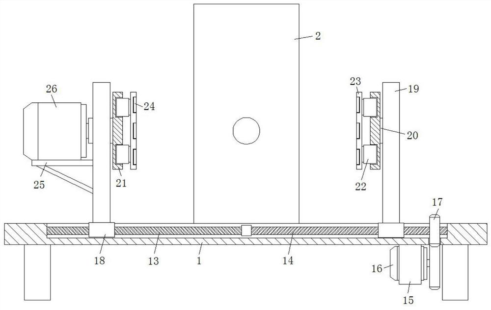
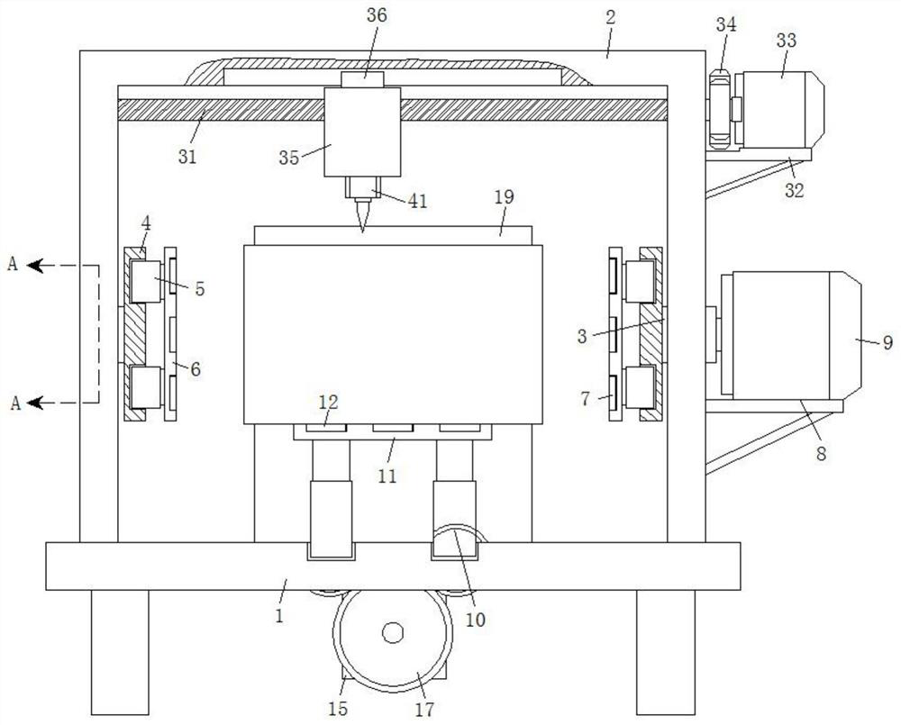
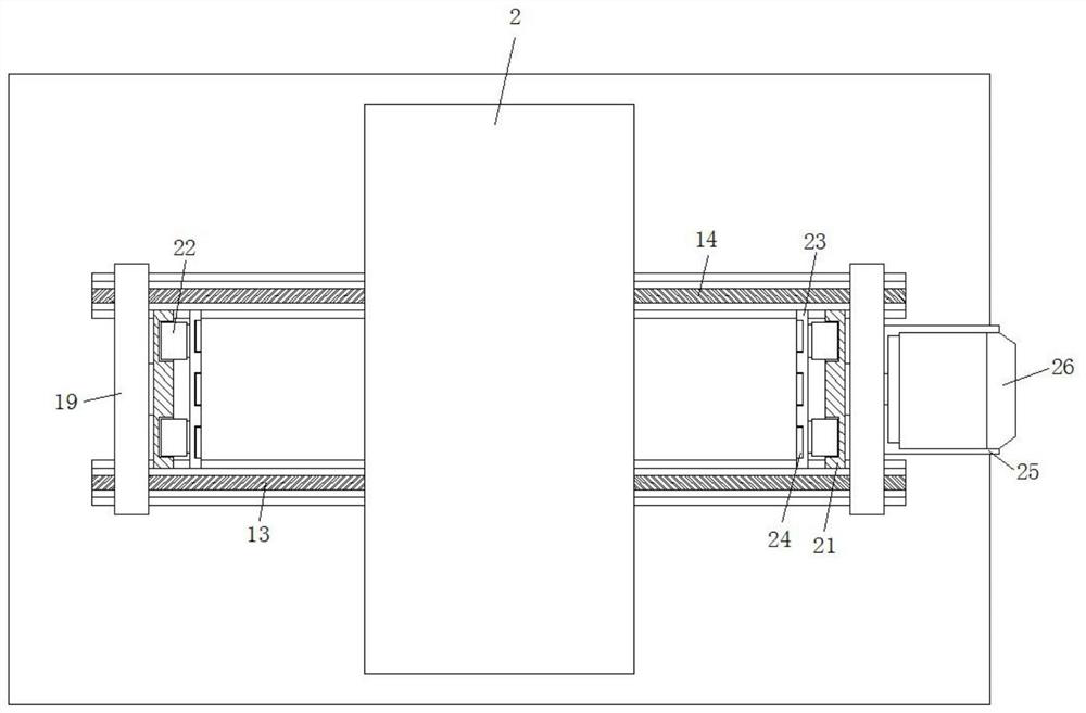
[0032] refer to Figure 1-7 , a high-efficiency drilling equipment with no dead angle for the production of power distribution cabinets, including a workbench 1, a mounting frame 2 is fixed in the middle of the top surface of the workbench 1 by screws, and the inner walls on both sides of the mounting frame 2 are rotatably connected with mounting columns-3 through rolling bearings , one end of the mounting column-3 is fixed with a mounting plate-4, and the upper and lower sides of the mounting plate-4 are away from the mounting column-3. The output end of the telescopic rod-5 is fixedly connected with an adsorption plate-6 through screws, and the other end of the adsorption plate-6 is fixed with an electromagnetic block-7 inside, and one side of the installation frame 2 is also fixedly connected with a horizontal frame-8 through screws, and the horizontal frame The top surface of -8 is fixedly connected with servo motor-9 by screws, the output end of servo motor-9 is fixedly c...

Embodiment 2

[0035] Such as figure 1 with 7 As shown, the present embodiment is basically the same as Embodiment 1. Preferably, a circular hole 27 is provided at the rotating connection between the mounting column 3 and the mounting plate 4 and the mounting column 20 and the mounting plate 21, and the circular hole 27 The inner wall is provided with a cylindrical groove 28, and the inner wall of the cylindrical groove 28 is slidably connected with a block 29, and an extruding spring 30 is fixedly connected between the block 29 and the bottom surface of the cylindrical groove 28, and the outer wall of the first mounting column 3 and the second 20 of the mounting column is also opened. There are draw-in slots, and the clamp blocks 29 are placed in the draw-in slots. The cylindrical slots 28 and the draw-in slots are all provided with four and evenly distributed on the inner wall of the circular hole 27 and the outer wall of the second mounting column 20.

[0036] In this embodiment, the con...

Embodiment 3

[0038] Such as Figure 1-7 As shown, this embodiment is basically the same as Embodiment 1. Preferably, electric telescopic rod one 5, electromagnetic block one 7, servo motor one 9, cylinder 10, electromagnetic block two 12, servo motor two 16, electric telescopic rod two 22 The control terminals of the electromagnetic block three 24, the servo motor three 26, the servo motor four 33, and the electric telescopic rod three 37 are all electrically connected with the controller, and the model of the controller is MAM-320.

[0039] In this embodiment, all the driving components in the device are electrically connected to the controller, so as to realize convenient control of the driving components, and further make the device run more stably.


PUM


Abstract

The invention discloses dead-corner-free efficient drilling equipment for power distribution cabinet production. The equipment comprises a working table. An installing frame is fixed to the middle ofthe top face of the working table through screws. First installing columns are connected to the inner walls of the two sides of the installing frame through rolling bearings correspondingly. First installing plates are fixed to the ends of the first installing columns correspondingly. First grooves are formed in the upper sides and the lower sides of the ends, away from the first installing columns, of the first installing plates. First electric telescopic rods are fixedly connected to the inner walls of the first grooves through screws. First adsorption plates are fixedly connected to the output ends of the first electric telescopic rods through screws. First electromagnetic blocks are fixed in the other ends of the first adsorption plates correspondingly. First horizontal frames are fixedly connected to the sides of the first installing frames through screws. First servo motors are fixedly connected to the top faces of the first horizontal frames through screws. The equipment is stable in operation, reasonable in design and high in automation degree, dead-corner-free drilling operation on the six faces of an electric control cabinet can be achieved after one-time feeding, and theworking efficiency of drilling of the electric control cabinet is greatly improved.

Description

technical field [0001] The invention relates to the technical field of power distribution cabinet processing equipment, in particular to a dead-angle-free high-efficiency drilling device for power distribution cabinet production. Background technique [0002] Power distribution cabinets are divided into power distribution cabinets, lighting distribution cabinets, and metering cabinets. They are the final equipment of the power distribution system. Power distribution cabinets are collectively referred to as motor control centers. , The motor control center is used in occasions where the load is concentrated and there are many circuits. When processing the power distribution cabinet, it is often necessary to drill holes on its surface to meet the requirements of installation, heat dissipation and wiring. [0003] After searching, the patent with application number 201820877730.3 discloses a drilling device for power distribution cabinet processing, including a base, the inner ...

Claims


Application Information

Patent Timeline
Patent Type & Authority Applications(China)
IPC IPC(8): B23B41/00B23Q3/15B23Q3/152B23Q5/22
CPCB23Q5/22B23Q3/15B23Q3/152B23B41/00
Inventor 庄连美陈万林
Owner ANHUI LANRUN AUTOMATION INSTR
Why Eureka
Try Eureka