Polishing head structure of polishing machine

A polishing head and polishing machine technology, which is applied in the field of polishing machines, can solve problems such as uneven pressure on ceramic discs, unstable fluctuations in equipment processing pressure, etc.

Pending Publication Date: 2020-12-29
SUZHOU HRT ELECTRONICS EQUIP TECH
View PDF0 Cites 1 Cited by
  • Summary
  • Abstract
  • Description
  • Claims
  • Application Information

AI Technical Summary

Problems solved by technology

[0002] Single-side polishing machine is currently the main equipment for processing hard and brittle materials such as monocrystalline silicon, polycrystalline silicon, electronic grade silicon, and sapphire. When the upper polishing head is used for pressure, the pressure of the polishing head cylinder will cause the processing pressure of the equipment to fluctuate and be unstable. , and the pressure on the ceramic disc is uneven

Method used


Image

  • Polishing head structure of polishing machine
  • Polishing head structure of polishing machine
  • Polishing head structure of polishing machine

Examples


Embodiment Construction

[0023] The present invention will be described in detail below with reference to the accompanying drawings and in combination with embodiments.

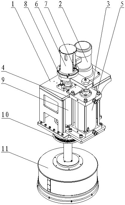
[0024] Such as figure 1 As shown, a polishing head structure of a polishing machine includes a bracket 1, a vertical motor 2, a driving gear 3, a driven gear 4, a cylinder assembly 5, an anti-rotation sleeve 6, a rotary joint assembly 7, a transition sleeve assembly 8, The upper disk shaft assembly 9, the organ cover 10 and the upper disk assembly 11, the vertical motor 2 is fixed on the bracket 1, the driving gear 3 is located inside the bracket 1 and is fixed to the output end of the vertical motor 2 Together, the driven gear 4 is fixed on the upper disc shaft assembly 9 and is engaged with the driving gear 3 for transmission. The cylinder body of the cylinder assembly 5 is fixed on the bracket 1, and the cylinder rod of the cylinder assembly 5 is connected by The block is connected to the transition shaft sleeve assembly 8, the u...


PUM


Abstract

The invention discloses a polishing head structure of a polishing machine. The polishing head structure comprises a support, a vertical motor, a driving gear, a driven gear and an air cylinder assembly, wherein the vertical motor is fixed to the support; the driving gear is located in the support and fixedly connected with the output end of the vertical motor; the driven gear is fixedly connectedto an upper disc shaft assembly and is in engaged transmission with the driving gear; a cylinder rod of the air cylinder assembly is connected with a transition shaft sleeve assembly; an anti-rotationsleeve is arranged at the upper end of the transition shaft sleeve assembly; a rotary connector assembly is arranged in the anti-rotation sleeve and connected with the upper disc shaft assembly; theupper disc shaft assembly is rotationally arranged in the support; the lower end of the upper disc shaft assembly is connected with an upper disc assembly; the upper disc assembly is located below thesupport; and an organ cover is arranged between the support and the upper disc assembly and connected to the upper disc shaft assembly. According to the polishing head structure, a balancing weight adjusting and pressurizing manner is adopted for replacing a traditional air cylinder pressurizing manner, pressurizing is more stable, and the pressurizing uniformity of a polishing head is better through a center auxiliary air cylinder pressurizing manner.

Description

technical field [0001] The invention relates to the technical field of polishing machines, in particular to a polishing head structure of the polishing machine. Background technique [0002] Single-side polishing machine is currently the main equipment for processing hard and brittle materials such as monocrystalline silicon, polycrystalline silicon, electronic grade silicon, and sapphire. When the upper polishing head is used for pressure, the pressure of the polishing head cylinder will cause the processing pressure of the equipment to fluctuate and be unstable. , and the pressure on the ceramic disc is uneven. [0003] In view of the above problems, the present invention provides a polishing head structure of a polishing machine, which adopts a counterweight adjustment pressurization method and a central auxiliary cylinder pressurization method to replace the traditional cylinder pressurization method, so that the polishing head pressurization uniformity is better. Cont...

Claims


Application Information

Patent Timeline
Patent Type & Authority Applications(China)
IPC IPC(8): B24B41/047B24B41/04B24B41/00
CPCB24B41/007B24B41/04B24B41/047
Inventor 孙文杰王和陆柄宇
Owner SUZHOU HRT ELECTRONICS EQUIP TECH
Why Eureka
Try Eureka