Remote transmission system of vertical-landing fixed-wing unmanned aerial vehicle
A long-distance transmission and unmanned aerial vehicle technology, which is applied in the transmission system, unmanned aircraft, rotorcraft, etc., can solve the problem of being unable to quickly understand the flight situation of the unmanned aerial vehicle, unable to separate the position information of the unmanned aerial vehicle and the video, Unable to adjust the flight status of the drone, etc., to achieve the effect of safe and convenient use, reduced space occupation, and easy handling and storage
- Summary
- Abstract
- Description
- Claims
- Application Information
AI Technical Summary
Problems solved by technology
Method used
Image
Examples
Embodiment 1
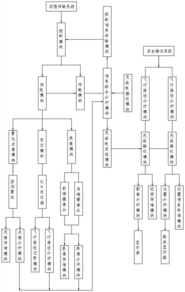
[0052] Embodiment 1: as figure 1 As shown, the present invention provides a technical solution for a remote transmission system of a fixed-wing unmanned aerial vehicle, a remote transmission system for a fixed-wing unmanned aerial vehicle, including a radar imaging module, a video recording module, a positioning module, a transmission module, and a power supply module , a control module, a background image receiving module and a background position receiving module;
[0053] The control module is respectively connected with the transmission module and the power supply module;
[0054] The power supply module is respectively connected with the radar imaging module, video recording module, positioning module and transmission module;
[0055] The radar imaging module includes a monitoring radar, an imaging analysis module and an imaging storage module, the imaging analysis module is connected to the transmission module, and the monitoring radar is connected to the imaging analys...
Embodiment 2
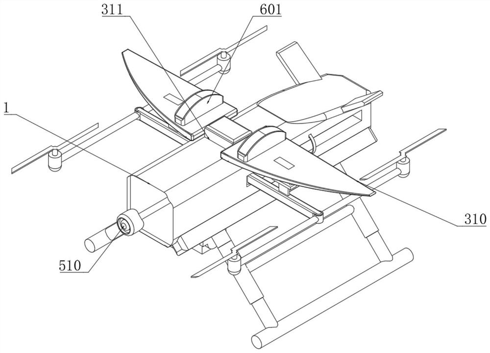
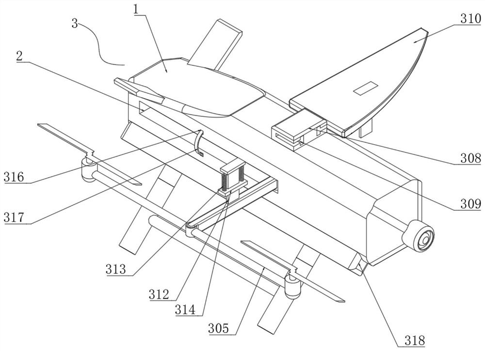
[0064] Embodiment 2: as Figure 2-10 As shown, the present invention provides a technical solution for a vertical fixed-wing unmanned aerial vehicle. A vertical fixed-wing unmanned aerial vehicle includes a box body 1, and the two ends of the box body 1 are symmetrically provided with fixed installation grooves 2, and the inner side of the fixed installation groove 2 is installed. There is a flight assembly 3, and the flight assembly 3 includes a support connecting rod 301, a rotation hole 302, a return spring 303, a connection port 304, a flight frame 305, a limit hole 306, a torsion spring 307, a fixed installation block 308, and a T-shaped clamping groove 309 , fixed wing 310, limit clamping plate 311, T-shaped clamping plate 312, limiting spring 313, clamping fixing ring 314, fixing clamping hole 315, clamping installation groove 316, protection spring plate 317, installation and fixing plate 318 , mounting threaded hole 319, external threaded rod 320 and connecting cylind...
PUM
 Abstract
Description
Claims
Application Information
 - R&D
- Intellectual Property
- Life Sciences
- Materials
- Tech Scout
- Unparalleled Data Quality
- Higher Quality Content
- 60% Fewer Hallucinations
Browse by: Latest US Patents, China's latest patents, Technical Efficacy Thesaurus, Application Domain, Technology Topic, Popular Technical Reports.
© 2025 PatSnap. All rights reserved.Legal|Privacy policy|Modern Slavery Act Transparency Statement|Sitemap|About US| Contact US: help@patsnap.com


