
Safe anaerobic fermentation tank

An anaerobic fermentation tank, a safe technology, applied in the direction of bioreactor/fermenter combination, specific-purpose bioreactor/fermenter, cleaning hollow objects, etc., can solve the problem of water shortage and increase the anaerobic fermentation time of organic matter , water vapor transmission speed slow down and other issues, to achieve the effect of maintaining water, reducing anaerobic fermentation time, and speeding up the transmission speed

Inactive Publication Date: 2020-12-29
王萍
View PDF0 Cites 1 Cited by
  • Summary
  • Abstract
  • Description
  • Claims
  • Application Information

AI Technical Summary

Problems solved by technology

[0002] Anaerobic fermentation is also biogas fermentation. Organic matter is placed into the interior of the fermenter, and after controlling the appropriate temperature and passing water vapor under anaerobic conditions, the organic matter reacts to generate flammable gas. There is a stirring mechanism to stir the organic matter and contact with microorganisms; in the process of anaerobic fermentation of organic matter using a fermenter in the prior art, since the organic matter is mixed with liquid water to form a viscous mixture, when the stirring force of the stirring mechanism increases At this time, the top layer of the mixture is scattered and splashed by the throwing force of the stirring mechanism. Since the opening of the steam delivery pipeline is set at a low height, the splashed mixture splashes into the opening, causing the opening of the pipeline for delivering water vapor to drop straight down and become smaller, while the water vapor The transmission speed of the organic matter is slowed down, resulting in insufficient water required by the organic matter, and increasing the anaerobic fermentation time of the organic matter

Method used


Image

  • Safe anaerobic fermentation tank
  • Safe anaerobic fermentation tank
  • Safe anaerobic fermentation tank

Examples


Embodiment 1

[0027] as attached figure 1 to attach Figure 5 Shown:

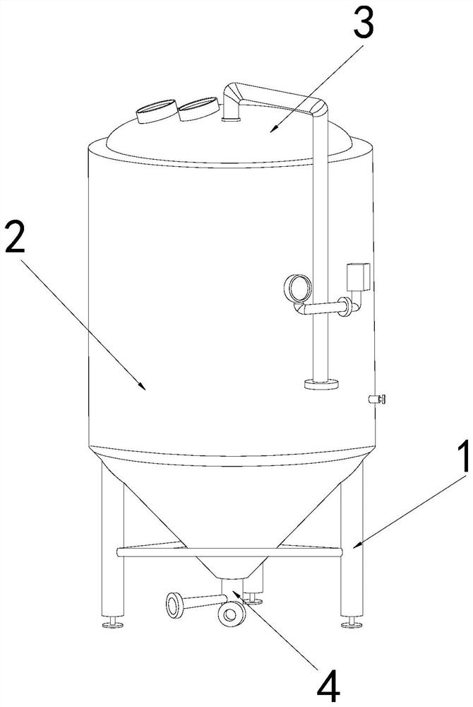
[0028] The invention provides a safe anaerobic fermentation tank, the structure of which includes a bracket 1, a tank body 2, a top cover 3, and a gas delivery pipe 4, the tank body 2 is vertically welded on the top of the bracket 1, and the top cover 3 is arranged on the top of the tank The center position of the top of the body 2, and the gas delivery pipe 4 is welded to the bottom of the tank body 2.

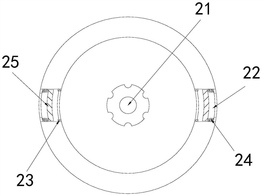
[0029] The tank body 2 is provided with a stirring rod 21, a steam pipe 22, a limit block 23, an elastic bar 24, and a moving block 25. The stirring rod 21 is installed in the middle of the tank body 2, and the steam pipe 22 runs through the tank body 2 The inner and outer walls on both sides of the middle part, the limiting block 23 is fixed on the inner wall of the steam pipe 22, the moving block 25 is arranged inside the steam pipe 22, and an elastic bar 24 is provided on the right side.

[0030] Wherein, the movi...

Embodiment 2

[0036] as attached Figure 6 to attach Figure 8Shown:

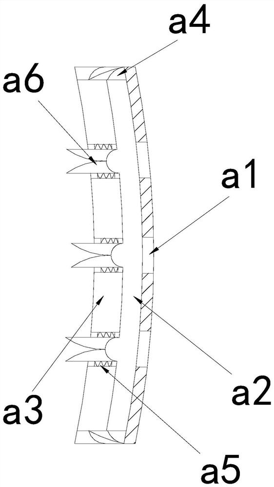
[0037] Wherein, the contact block a4 is provided with a connection block e1, a partition e2, an opening e3, a pole e4, and a cleaning block e5, the opening e3 runs through the top of the contact block a4, and the partition e2 is arranged inside the contact block a4, The connection block e1 is located between the inner bottom of the contact block a4 and the bottom surface of the partition e2, the support rod e4 is fixed on the top surface of the partition e2 through the opening e3, and the cleaning block e5 is installed on the top of the support rod e4. The top surface of the removal block e5 is an undulating surface, which is conducive to increasing the contact area with the inner wall of the steam pipe 22, speeding up the removal of the mixture on the inner wall of the steam pipe 22, and keeping the steam pipe 22 unblocked.

[0038] Wherein, the opening e3 is provided with a block r1, a baffle r2, and a spring r3, the...


PUM


Abstract

The invention discloses a safe anaerobic fermentation tank. The safe anaerobic fermentation tank structurally comprises a bracket, a tank body and a top cover; the top layer of a tank body mixture isscattered and splashed by throwing force of a stirring mechanism, and the splashed mixture is splashed into an opening of a steam pipeline, so that the opening diameter of the steam pipeline becomes smaller; a moving block is pushed by gas to move on the inner wall of the steam pipeline; a clearing plate pushes a mixture in the steam pipeline, so that accumulation of the mixture in the steam pipeline is reduced, smoothness of the steam pipeline is kept, the transmission speed of water vapor is increased, moisture required by organic matter is kept, and the anaerobic fermentation time of the organic matter is shortened; as the inner wall diameter of the steam pipeline is gradually reduced, the mixture is easily condensed on the inner wall of the pipeline; a contact block is in contact withthe inner wall of the steam pipeline, and a clearing block clears the mixture on the inner wall of the pipeline, thereby being beneficial to reducing condensation of the mixture in the pipeline and keeping the moving block freely moving in the pipeline; and the moving block is accelerated to push the mixture in the pipeline.

Description

technical field [0001] The invention belongs to the field of anaerobic fermentation equipment, and more specifically, relates to a safe anaerobic fermentation tank. Background technique [0002] Anaerobic fermentation is also biogas fermentation. Organic matter is placed into the interior of the fermenter, and after controlling the appropriate temperature and passing water vapor under anaerobic conditions, the organic matter reacts to generate flammable gas. There is a stirring mechanism to stir the organic matter and contact with microorganisms; in the process of anaerobic fermentation of organic matter using a fermenter in the prior art, since the organic matter is mixed with liquid water to form a viscous mixture, when the stirring force of the stirring mechanism increases At this time, the top layer of the mixture is scattered and splashed by the throwing force of the stirring mechanism. Since the opening of the steam delivery pipeline is set at a low height, the splashe...

Claims


Application Information

Patent Timeline
Patent Type & Authority Applications(China)
IPC IPC(8): C12M1/02C12M1/04C12M1/107C12M1/00B08B9/043
CPCB08B9/0436C12M21/04C12M27/02C12M29/06C12M39/00
Inventor 王萍
Owner 王萍
Learn More