Tension-anchor type structural steel cantilever supporting operation scaffold combined system and construction method

A technology of cantilevered scaffolding and construction method, which is applied to the scaffolding supported by the building structure, the accessories of the scaffolding, the formwork/formwork/work frame, etc. problem, to achieve the effect of simple structure and easy operation

Inactive Publication Date: 2020-12-29
王振奇
View PDF0 Cites 10 Cited by
  • Summary
  • Abstract
  • Description
  • Claims
  • Application Information

AI Technical Summary

Problems solved by technology

Formwork support scaffolding, cable wind ropes, conveying pipes for pumping concrete and mortar, etc. shall not be fixed on the frame body; according to the understanding of the above specification provisions, the structural component formwork support scaffolding and operating scaffolding must be designed and erected separately; in order to ensure that the frame body Safety, the formwork support scaffold and the operation scaffold cannot be connected; in actual construction, in order to meet the specification requirements and ensure construction safety, the formwork support scaffold and the operation scaffold must be designed and erected separately. The investment of materials and other resources has also greatly affected the construction progress; for the anchorage length of 1.25 times of the anchorage length of the I-steel main girder of the traditional section steel cantilevered scaffold is laid and anchored on the floor, the bearing capacity of the cantilevered end of the I-steel beam is ...

Method used


Image

  • Tension-anchor type structural steel cantilever supporting operation scaffold combined system and construction method
  • Tension-anchor type structural steel cantilever supporting operation scaffold combined system and construction method
  • Tension-anchor type structural steel cantilever supporting operation scaffold combined system and construction method

Examples


Embodiment 1

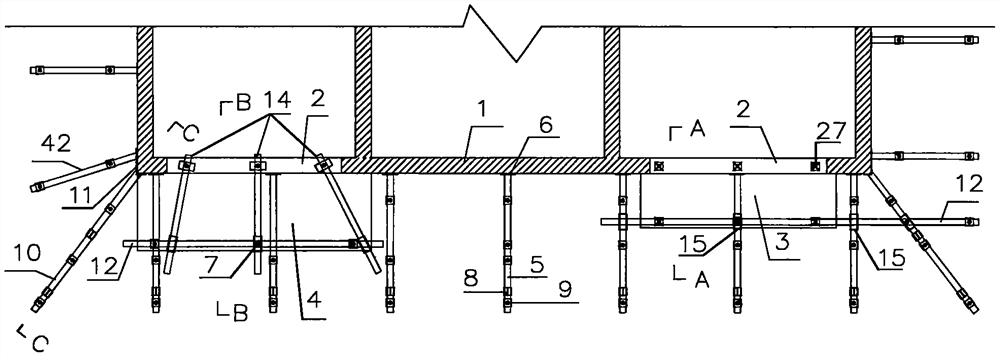
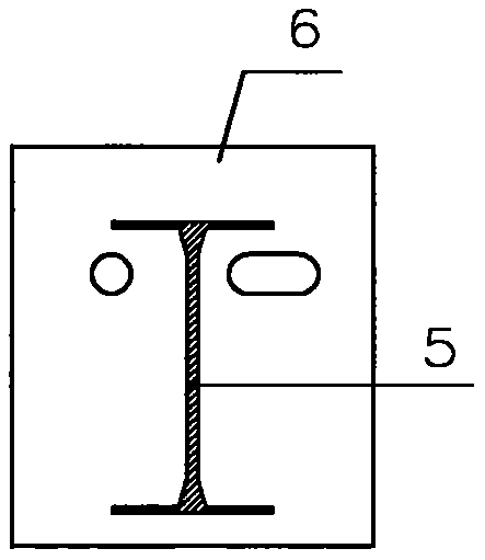
[0045] The working condition of this embodiment is the bay window part of the concrete structure, combined with Figure 1-Figure 12 Illustrate this embodiment, in this embodiment, a combination system and construction method of anchor-type steel cantilevered support work scaffolding, figure 1 It is a schematic diagram of the plane layout of the steel foundation and accessories, Figure 2 to Figure 11 Construct large mockups for each fitting, Figure 12It is a schematic diagram of the cross-sectional structure of A-A of this embodiment; by embedding the pre-embedded fixing device 16, it is pre-embedded to the designated position of the structure in advance (two I-beam anchorage positions are pre-embedded, and each flower basket tie rod upper structure hanging point One is pre-embedded, and one is pre-embedded at each position of the scaffolding wall parts), and the anchor end plate 6 is welded to the end of the I-beam main beam 5, and the high-strength bolts used in conjunctio...

Embodiment 2

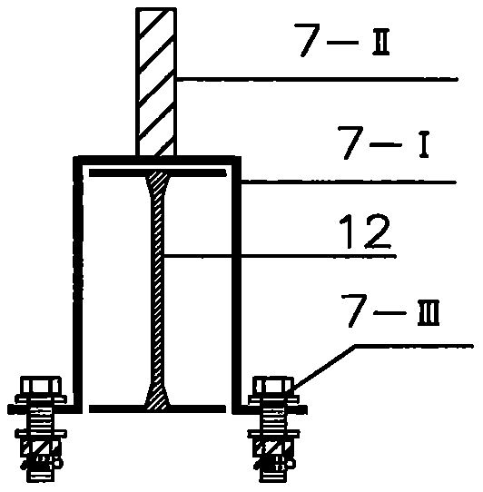
[0047] In combination with embodiment 1 and Figure 13 Describe this embodiment, a combination system and construction method of an anchor-type steel cantilever support scaffolding operation involved in this embodiment. The advantage is that the I-steel support beam 14 is set at the position of the protruding balcony slab of the structure, the I-steel support beam is used to fix and the pole base device 13 is used, and the indoor proximal end of the I-steel support beam 14 is anchored in the lower part. The upper part of the floor or beam supported by the wall further supports the outdoor remote end of the I-beam support beam 14 on the main node of the scaffold pole 21 and the support cross bar 20. If the I-beam primary and secondary beams are connected by aluminum mold support If the I-shaped steel primary and secondary beams are fixed and the vertical pole base device 7 is used to lock the primary and secondary beams to each other, if the I-shaped steel primary and secondary...

Embodiment 3

[0049] In combination with embodiment 1 and Figure 14 Describe this embodiment, which involves an anchor-type steel cantilever support scaffold combination system and construction method in this embodiment. The difference of Example 1 is that the I-steel male corner beam 10 is welded to the I-steel male corner beam end plate 11, and is anchored to the male corner of the outer wall surface of the structure or the male corner of the beam side through a pre-embedded fixing device 16. position, the angle of the I-beam male angle beam is 45°~60°, which can be adjusted according to actual needs. Two detachable steel beam hanger plate devices 8 are arranged on the I-beam male angle beam 10. Set up a pre-embedded bolt fixing device on both sides of the external corner of the top outer wall and install the ring head bolts, and connect the two detachable steel beam lugs of the I-steel male corner beam 10 through the flower basket pull rod one after the other. The device 8 is connected...


PUM

PropertyMeasurementUnit
Lengthaaaaaaaaaa
Diameteraaaaaaaaaa

Abstract

The invention discloses a tension-anchor type structural steel cantilever supporting operation scaffold combined system and a construction method, and relates to the building construction technology.The tension-anchor type structural steel cantilever supporting operation scaffold combined system specifically comprises matched devices such as I-shaped steel primary and secondary beams, detachablelifting lug devices, primary and secondary beam fixing and vertical rod base devices, steel pipe vertical rod free-combination type fixing base devices, embedded bolt fixing devices, flower basket pull rod devices and wall-connecting short rod devices. A traditional structural steel cantilever scaffold is improved through the devices, a supporting operation scaffold is erected on the improved cantilever I-shaped steel primary and secondary beams, and the combined system with the two functions of a structural cantilever component formwork supporting scaffold and an outer wall operation scaffoldis achieved. The tension-anchor type structural steel cantilever supporting operation scaffold combined system is simple in structure and easy and convenient to operate, the cantilever component formwork supporting scaffold and the outer wall operation scaffold are organically combined together, and the construction progress can be effectively accelerated while the investment of resources such aslabor and materials is greatly reduced on the premise that scaffold erecting and using safety and reliability are guaranteed.

Description

technical field [0001] The invention belongs to the field of construction engineering, and in particular relates to a combined system and construction method of an anchor-type steel cantilevered support scaffolding operation. Background technique [0002] In the field of construction engineering, especially in the construction of high-rise buildings, steel cantilevered scaffolds are often used as work scaffolds or structural overhanging components (bay windows, balconies, air-conditioning panels, roof overhangs, etc.) The erection requirements of scaffolding and formwork support scaffolding, in the "Technical Specifications for Safety of Fastener Type Steel Pipe Scaffolding in Building Construction" (JGJ130--2011), Article 9.0.5 stipulates that the construction load on the working layer should meet the design requirements, Do not overload. Formwork support scaffolding, cable wind ropes, conveying pipes for pumping concrete and mortar, etc. shall not be fixed on the frame bo...

Claims


Application Information

Patent Timeline
IPC IPC(8): E04G3/18E04G3/20E04G5/00E04G5/04E04G5/16E04G13/06
CPCE04G3/18E04G3/20E04G5/00E04G5/007E04G5/046E04G5/16E04G13/06E04G13/066E04G13/068
Inventor 王振奇路海龙
Owner 王振奇
Why Eureka
Try Eureka