Clutch operating system and vehicle

An operating system and clutch technology, applied in clutches, magnetic drive clutches, non-mechanical drive clutches, etc., can solve the problems of lack of closed-loop control, affecting the driving experience, and inability to adjust the speed and specific position of the release bearing, so as to improve the driving experience. , avoid turbulence, optimize the effect of control

Inactive Publication Date: 2020-12-29
ZHEJIANG JIZHI NEW ENERGY AUTOMOBILE TECH CO LTD +1
View PDF10 Cites 0 Cited by
  • Summary
  • Abstract
  • Description
  • Claims
  • Application Information

AI Technical Summary

Problems solved by technology

There are mainly two kinds of traditional automobile clutch operating mechanisms, one is mechanical operating mechanism and the other is hydraulic operating structure. Since these two operating mechanisms do not have the function of self-maintaining in the separated state, they cannot be applied to new vehicles with multiple power sources. In energy vehicles, it is necessary to develop a new clutch operating mechanism suitable for new energy vehicles
[0003] The authorized announcement number is CN202991944U, and the patent name is a clutch operating mechanism, which provides a new clutch operating structure suitable for new energy vehicles, such as figure 1 As shown, it includes a cylindrical support seat, a permanent magnet, a main electromagnet and a positioning electromagnet. The cylindrical support seat is loosely fitted on the transmission input shaft and connected with the clutch release bearing. The magnetic field interacted by the magnets acts on the cylindrical supporting seat, and acts on the release bearing through the cylindrical supporting seat, so as to realize the operation of the clutch. However, the clutch operating mechanism cannot guarantee the cylindrical bearing when the main electromagnet is not powered or magnetic. The support seat and the release bearing are in constant contact. When the whole vehicle is running, the cylindrical support seat may move on the shaft and contact other parts, resulting in abnormal noise. Moreover, the operating mechanism lacks closed-loop control, and the release bearing cannot be adjusted according to the actual working conditions. The speed and specific position of the movement cannot be controlled in a timely manner, which affects the driving experience

Method used


Image

  • Clutch operating system and vehicle
  • Clutch operating system and vehicle

Examples


Embodiment 1

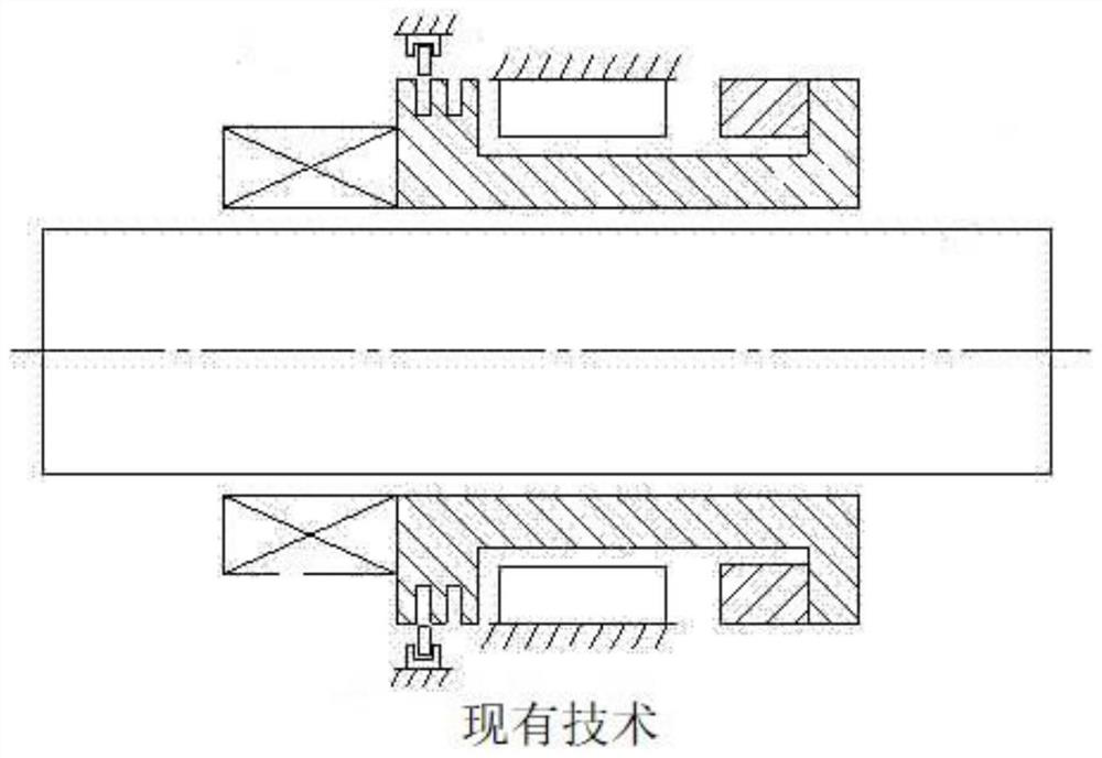
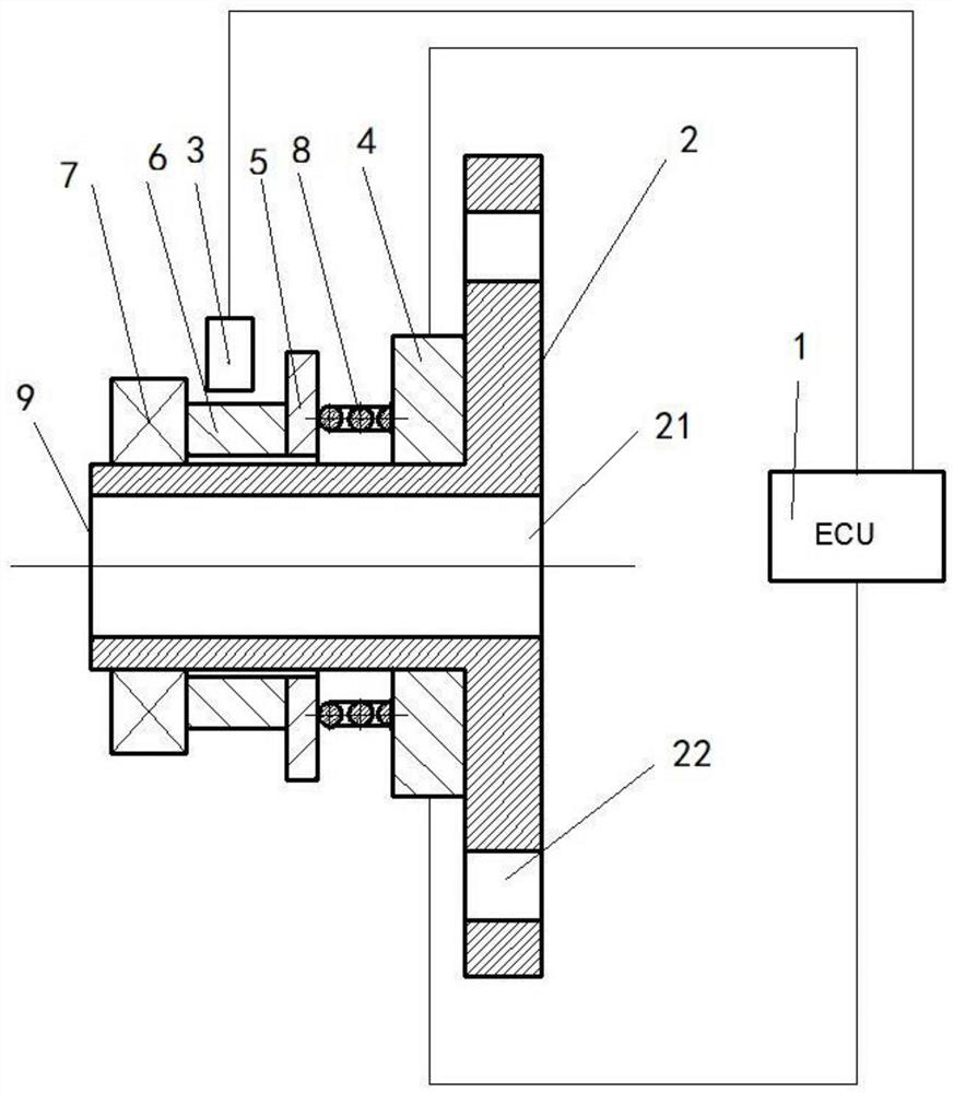
[0033] Traditional clutch actuators have been difficult to meet the current electrification requirements, such as figure 1 As shown, a clutch operating mechanism provided by the prior art can be applied to new energy vehicles with multiple power sources, and the magnetic force generated by the inductance coil is used as the execution force to push the clutch separation finger, but the operating mechanism cannot solve the problem of The problem of abnormal noise caused by parts colliding in the shaft system, and because of the lack of closed control, the movement speed and specific position of the release bearing cannot be adjusted according to the actual working conditions, and real-time control cannot be performed, which affects the driving experience. Therefore, the present embodiment provides a clutch operating system, and the clutch operating device can solve the problems mentioned above, such as figure 2 As shown, the clutch operating system includes an operating device ...

Embodiment 2

[0045] Embodiment 2 is the preferred embodiment of embodiment 1

[0046] Compared with Embodiment 1, this embodiment is preferred in that: preferably, there is one pre-compressed elastic member, and specifically, the pre-compressed elastic member is a pre-compressed coil spring, and the transmission input shaft is arranged at the The hollow part of the preloaded coil spring. The beneficial effects achieved by the clutch operating system provided in this embodiment are basically the same as those in Embodiment 1, so details will not be repeated here.

Embodiment 3

[0047] Embodiment 3 is an optional embodiment of embodiment 2

[0048] Compared with Embodiment 2, this embodiment is optional in that: as an option, there are multiple pre-compression elastic members 8, specifically, the pre-compression elastic members are pre-compression springs, and pre-compression can be set according to actual needs There are three elastic members 8, which are arranged at 120° to each other in the radial direction around the transmission input shaft. The beneficial effects achieved by the clutch operating system provided in this embodiment are basically the same as those in Embodiment 1, so details will not be repeated here.


PUM


Abstract

The invention discloses a clutch operating system. The clutch operating system comprises an operating device and a control unit; the operating device comprises a base and a position sensor, and a n electromagnet, a permanent magnet, a sleeve and a release bearing which are sequentially arranged on the base in a sleeved mode; the electromagnet is electrically connected with the control unit, has the same magnetic pole as the permanent magnet, and is used for pushing the permanent magnet to move under a power-on condition; a pre-pressing elastic piece is arranged between the electromagnet and the permanent magnet and used for keeping constant contact between the sleeve and the release bearing; the position sensor is connected with the control unit and is used for detecting position information of the release bearing and transmitting the position information to the control unit; and the control unit controls the magnetism of the electromagnet according to the position information. The invention further discloses a vehicle. The control unit and the position sensor are adopted to control the magnitude of electromagnetism, and therefore closed-loop control over the movement speed and position of an executing mechanism is achieved, optimal control over the clutch is achieved, and the driving experience is improved.

Description

technical field [0001] The invention relates to the technical field of automobiles, in particular to a clutch operating system and a vehicle. Background technique [0002] As the trend of automobile electrification becomes more and more clear, the electrification level of various parts of automobiles is also getting higher and higher. The combination and separation of the automobile clutch is determined by the position of the clutch release bearing. The clutch release bearing is set outside the transmission input shaft. The operating mechanism of the automobile clutch realizes the control of the state of the automobile clutch by driving the clutch release bearing to move along the transmission input shaft. . There are mainly two kinds of traditional automobile clutch operating mechanisms, one is mechanical operating mechanism and the other is hydraulic operating structure. Since these two operating mechanisms do not have the function of self-maintaining in the separated sta...

Claims


Application Information

Patent Timeline
Patent Type & Authority Applications(China)
IPC IPC(8): F16D27/01F16D27/10
CPCF16D27/004F16D27/01F16D27/10
Inventor 何群汪小云谢文强
Owner ZHEJIANG JIZHI NEW ENERGY AUTOMOBILE TECH CO LTD
Why Eureka
Try Eureka