Energy saver of LED dimming energy-saving lamp
An energy-saving device and energy-saving lamp technology, which is applied in the direction of light source fixing, lighting device, and lighting device components, etc., can solve the problems of life impact, easy heat generation, and efficiency reduction, and achieve the effect of convenient maintenance.
- Summary
- Abstract
- Description
- Claims
- Application Information
AI Technical Summary
Problems solved by technology
Method used
Image
Examples
Embodiment 1
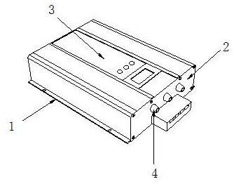
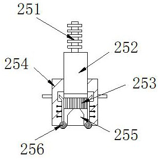
[0024] see Figure 1-Figure 5 , the specific embodiments of the present invention are as follows: an LED dimming energy-saving lamp energy saver, its structure includes a fixed seat 1, a body 2, a control panel 3, and a maintenance plug 4, the top surface of the fixed seat 1 is welded to the bottom surface of the body 2, The bottom surface of the control board 3 is fixedly installed on the top surface of the body 2, and the left side of the maintenance plug 4 is embedded in the right side of the body 2; The voltage reducer 25 and the output head 26, the power connector 22 is embedded in the right side of the casing 21, the bottom surface of the setting seat 23 is fixedly connected with the inside of the casing 21, and one side of the voltage reducer 25 is connected to the connection cable 24 through a connecting cable 24. The left side of the electric head 22 is connected, the voltage reducer 25 is embedded in the top surface of the setting seat 23, the output head 26 is embed...
Embodiment 2
[0030] see Figure 6-Figure 7 The specific embodiment of the present invention is as follows: the ejector 255 includes a fixed shell B1, a power board B2, an electromagnet B3, a recovery ring B4, a push rod B5, and a magnetic plate B6, and the power board B2 is embedded in the fixed shell B1 The top, the bottom of the electromagnet B3 is fixedly installed inside the fixed shell B1, the outer ring of the recovery ring B4 is fixedly connected with the inside of the fixed shell B1, the bottom of the ejector rod B5 is fixedly connected with the top of the magnetic plate B6, and the recovery ring B4 The bottom is superimposed with the top of the magnetic plate B6, and the magnetism produced by the electromagnet B3 is opposite to the magnetic force of the magnetic plate B6 when the electromagnet B3 is energized.
[0031] Wherein, the recovery ring B4 includes a ring shell B41, a fixed plate B42, a movable plate B43, an elastic plate B44, an inner shaft B45, a winding block B46, and ...
PUM
 Abstract
Description
Claims
Application Information
 - R&D Engineer
- R&D Manager
- IP Professional
- Industry Leading Data Capabilities
- Powerful AI technology
- Patent DNA Extraction
Browse by: Latest US Patents, China's latest patents, Technical Efficacy Thesaurus, Application Domain, Technology Topic, Popular Technical Reports.
© 2024 PatSnap. All rights reserved.Legal|Privacy policy|Modern Slavery Act Transparency Statement|Sitemap|About US| Contact US: help@patsnap.com


