Optical device rotation angle detection method, rotation angle detection device and camera module

A technology of rotation angle detection and optical devices, which is applied in the direction of measuring devices, optics, projection devices, etc., can solve problems such as coil warping, scratching, and lower detection accuracy, so as to reduce the complexity of the bending process, improve accuracy, The effect of ensuring machining accuracy

Active Publication Date: 2020-12-29
HUAWEI MACHINERY
View PDF6 Cites 0 Cited by
  • Summary
  • Abstract
  • Description
  • Claims
  • Application Information

AI Technical Summary

Problems solved by technology

In this way, the first detection device 004 needs to be installed on the first surface ① formed after the flexible circuit board is bent, and the second detection device 005 needs to be installed on the third surface ③ formed after the flexible circuit board is bent. The first detection device 004, the second detection device 005, and the flexible circuit board of the coil are bent twice to form three surfaces, which easily leads to the following technical problems: the double bending process of the flexible circuit board is complicated, and after two times of bending The flexible circuit board is easy to cause the coil to warp, and it is not easy to be arranged opposite to the corresponding magnet, which will cause scratches and reduce the detection accuracy
[0007] If in order to reduce the process complexity of bending the flexible circuit board, that is, the flexible circuit board is only bent once to form two surfaces, it is necessary to install the second detection device 005 on the second surface formed after the flexible circuit board is bent, However, when the second detection device 005 is installed on the second surface formed after the flexible circuit board is bent, either the rotation position of the optical device along the X direction cannot be determined, or the optical device rotates around the X direction or the Y direction. , the second detection device 005 has a voltage change, which requires a decoupling method to determine the rotation angle of the optical device around the X direction. In the prior art, there is no decoupling method to determine the rotation angle of the optical device around the X direction. to determine

Method used


Image

  • Optical device rotation angle detection method, rotation angle detection device and camera module
  • Optical device rotation angle detection method, rotation angle detection device and camera module
  • Optical device rotation angle detection method, rotation angle detection device and camera module

Examples


Embodiment Construction

[0058] The embodiment of the present application relates to a method for detecting a rotation angle of an optical device, a device for detecting a rotation angle, a camera module, and a mobile terminal. The method for detecting a rotation angle of an optical device, a device for detecting a rotation angle, a camera module, and a mobile terminal will be described in detail below in conjunction with the accompanying drawings. .

[0059] The concepts involved in the above embodiments are briefly described below:

[0060] Flexible printed circuit board (Flexible Printed Circuit, FPC board).

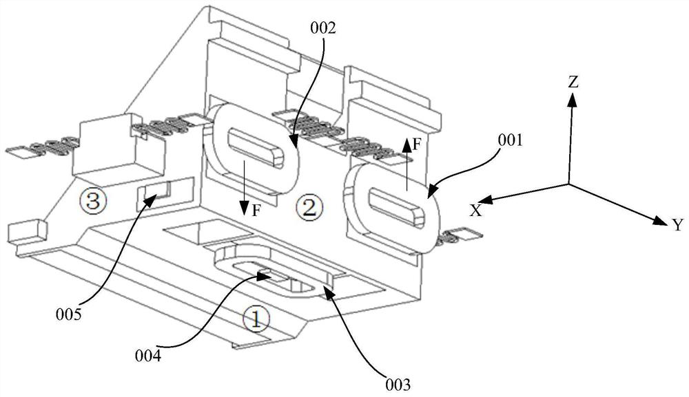
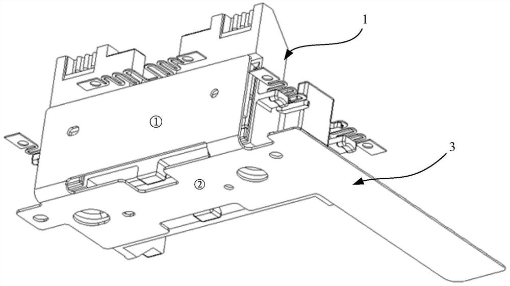
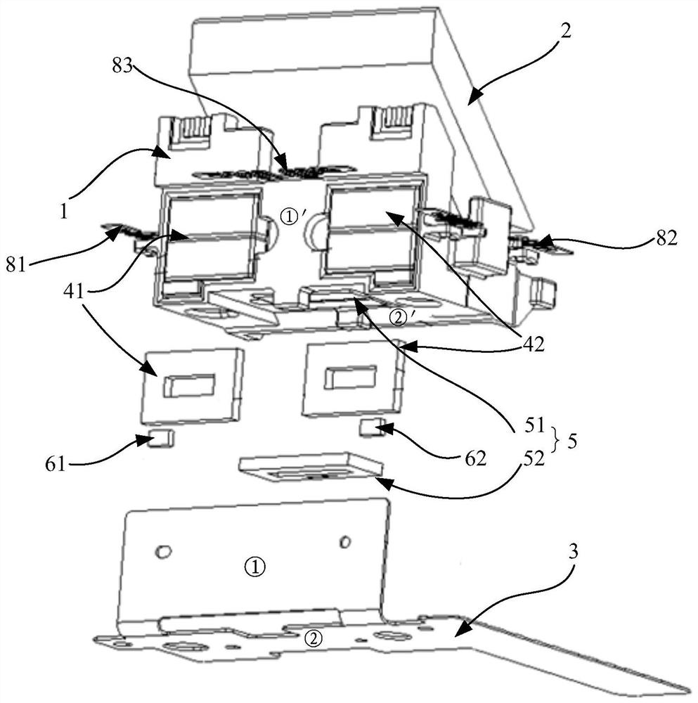
[0061] In the first aspect, the embodiment of the present application provides a method for detecting the rotation angle of an optical device, referring to figure 2 , image 3 and Figure 4 , the optical device 2 can be driven by the first driving mechanism to rotate around the first axis, and can be driven by the second driving mechanism to rotate around the second axis, and the second a...


PUM


Abstract

The embodiment of the invention provides an optical device rotation angle detection method, a rotation angle detection device and a camera module, and relates to the technical field of optical anti-shake. The optical device rotation angle detection method comprises the steps of detecting the rotation angle of an optical device around a first axis; acquiring a first Hall value output by a first position sensor, and acquiring a second Hall value output by a second position sensor; calculating the difference between the first Hall value and the second Hall value to obtain a Hall difference value;and determining the angle of the optical device when the optical device rotates around the first axis according to the corresponding relation between the Hall difference value and the rotation anglevalue of the optical device, wherein a second axis is perpendicular to the first axis.

Description

technical field [0001] The present application relates to the field of optical anti-shake technology, and in particular to a method for detecting a rotation angle of an optical device, a device for detecting a rotation angle, a camera module, and a mobile terminal. Background technique [0002] Nowadays, optical image stabilization technology has been widely used in mobile terminals, such as mobile phones, tablet computers, and vehicle-mounted systems. Optical image stabilization can effectively reduce blurred photos taken under shaking conditions. [0003] The existing one is to drive the optical device to rotate through the drive module to achieve optical anti-shake, refer to figure 1 , the drive module includes a first drive structure for driving the carrier mounted with optical devices (not shown) relative to the housing (not shown) to rotate around the first axis X, and for driving the mount mounted with optical devices The second driving structure in which the carrier...

Claims


Application Information

Patent Timeline
Patent Type & Authority Applications(China)
IPC IPC(8): G01B7/30G03B5/00
CPCG01B7/30G03B5/00
Inventor 郭利德吴雨顺李坤宜
Owner HUAWEI MACHINERY
Why Eureka
Try Eureka