
Current detection circuit based on Hall current sensor

A technology of current detection circuit and Hall current, which is applied to the components of electrical measuring instruments, voltage/current isolation, instruments, etc., can solve the problems of high cost, troublesome installation, and easy interference of detection results, so as to reduce the detection cost , convenient and fast detection, avoiding the effect of being easily disturbed

Pending Publication Date: 2020-12-29
SHENZHEN X TEC TECH CO LTD
View PDF0 Cites 5 Cited by
  • Summary
  • Abstract
  • Description
  • Claims
  • Application Information

AI Technical Summary

Problems solved by technology

[0004] The purpose of the present invention is to provide a current detection circuit based on a Hall current sensor, which aims to solve the problem that the detection cost is too high, the installation is troublesome, and the detection results are easily disturbed when the current sensor is used to detect the current in the prior art. question

Method used


Image

  • Current detection circuit based on Hall current sensor
  • Current detection circuit based on Hall current sensor
  • Current detection circuit based on Hall current sensor

Examples


Embodiment approach

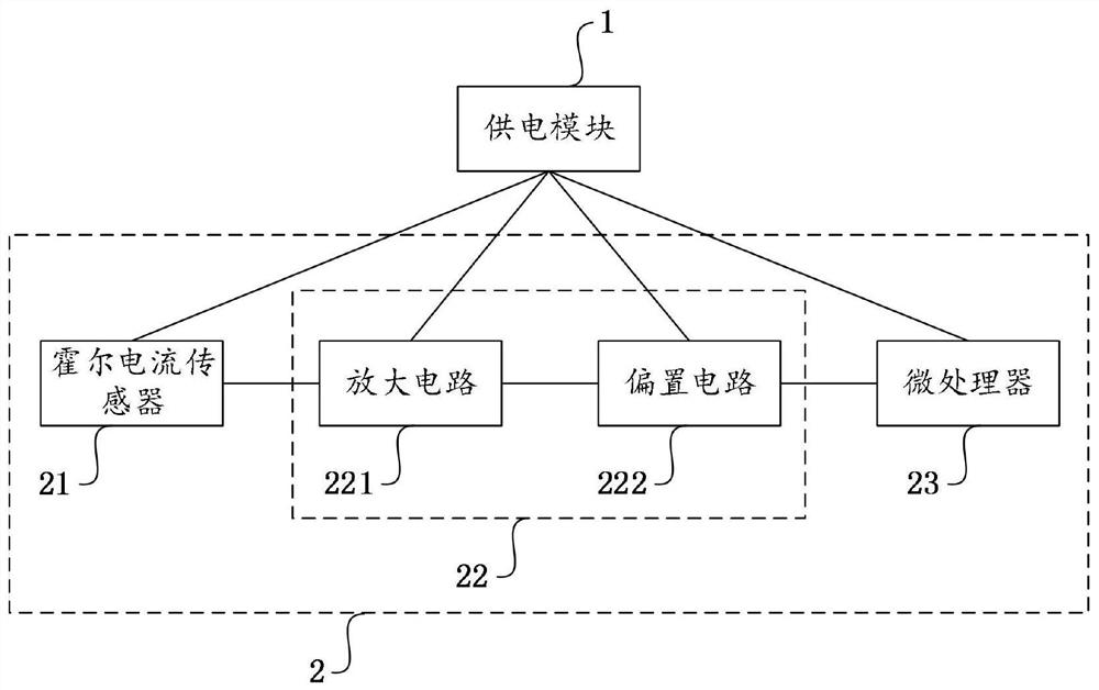
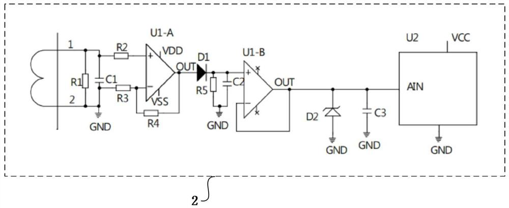
[0025] Please also refer to figure 1 and figure 2 , as an embodiment of the present invention, the signal adjustment circuit 22 includes an amplifier circuit 221 and a bias circuit 222; one end of the amplifier circuit 221 is connected to the output end of the Hall current sensor 21, and the other end of the amplifier circuit 221 is connected to the bias circuit One terminal of the circuit 222 and the other terminal of the bias circuit 222 are connected to the input terminal of the microprocessor 23 . Among them, the amplification circuit 221 is used to increase the output power of the signal, and can amplify the induction signal generated by the Hall current sensor 21 according to the measured current signal, so as to facilitate its detection. The bias circuit 222 is used to increase the signal amplitude, At the same time, the induction signal is converted into a stable DC signal to adapt to the input characteristics of the microprocessor 23 .

[0026] Specifically, the am...


PUM


Abstract

The invention relates to the technical field of current sensors, and discloses a current detection circuit based on a Hall current sensor. The current detection circuit comprises a power supply moduleand a detection module, and the power supply module supplies power to the detection module; the detection module comprises the Hall current sensor, a signal adjusting circuit and a microprocessor; the Hall current sensor is used for generating induction signals according to detected current signals; the signal adjusting circuit is used for adjusting the induction signals generated by the Hall current sensor into analog signals capable of being matched with the microprocessor; and the microprocessor is used for converting the analog signals into digital signals and is used detecting the magnitude of the detected current signals according to the digital signals and outputting the detected current signals. According to the current detection circuit based on the Hall current sensor, the to-be-detected current can be conveniently and rapidly detected, the detection cost is greatly reduced, meanwhile, the circuit structure is simple, the reliability is high, and the problem that the detection result is easily interfered in the detection process is also avoided.

Description

technical field [0001] The invention relates to the technical field of current sensors, in particular to a current detection circuit based on a Hall current sensor. Background technique [0002] The current sensor is a detection device that can sense the information of the measured current, and can convert the information sensed by the detection into an electrical signal that meets certain standards or other required forms of information output according to certain rules, so as to meet the Information transmission, processing, storage, display, recording and control requirements. [0003] Current sensors are also called magnetic sensors, which can be used in household appliances, smart grids, electric vehicles, wind power generation, etc. Many magnetic sensors are used in our lives, such as computer hard drives, compasses, and household appliances. When the existing current sensor detects the current, the voltage signal or current signal needs to be digitally converted by P...

Claims


Application Information

Patent Timeline
Patent Type & Authority Applications(China)
IPC IPC(8): G01R19/25G01R15/20G01R1/30
CPCG01R1/30G01R15/202G01R19/25
Inventor 张廷锴肖文佑
Owner SHENZHEN X TEC TECH CO LTD
Learn More