Precoated sand casting mold

A casting mold and coated sand technology, which is applied in the direction of manufacturing tools, casting equipment, casting molding equipment, etc., can solve problems such as lack of materials, inconvenient installation, fixing and disassembly, and insufficient tightness of internal molds

Active Publication Date: 2021-01-01
HEBEI HONOR MECHANICAL MOLD
View PDF12 Cites 5 Cited by
  • Summary
  • Abstract
  • Description
  • Claims
  • Application Information

AI Technical Summary

Problems solved by technology

[0003] 1. The existing device needs to align the upper and lower mold clamps when casting is required and then fix the two. In the traditional fixing, the two are fixed together by using multiple screws, which is not convenient for users to install. Fixing and later disassembly waste time and reduce work efficiency;
[0004] 2. At the same time, because most of the traditional equipment is fixed by screws, the fastening degree between the internal molds is not tight enough, which affects the normal use of the equipment;
[0005] 3. During the process of putting the material into the mold for injection molding, because the temperature in the material is too high and contains a small amount of water, there will be water vapor remaining in the mold. When the water vapor forms water droplets and mixes into the material, it will cause the material to be short of material phenomenon, which leads to errors in the accuracy of the injection mold. At the same time, in the process of injection mold in cold winter, due to the large difference between the temperature in the mold cavity and the outside temperature, the water vapor in the material is liquefied to form water droplets. Water droplets will be mixed into the material, resulting in a lack of material

Method used


Image

  • Precoated sand casting mold
  • Precoated sand casting mold
  • Precoated sand casting mold

Examples


Embodiment Construction

[0034] The technical solutions in the embodiments of the present invention will be clearly and completely described below in conjunction with the accompanying drawings in the embodiments of the present invention. Apparently, the described embodiments are only some, not all, embodiments of the present invention. Based on the embodiments of the present invention, all other embodiments obtained by persons of ordinary skill in the art without making creative efforts belong to the protection scope of the present invention.

[0035] see Figure 1 to Figure 8 , the present invention provides a technical solution:

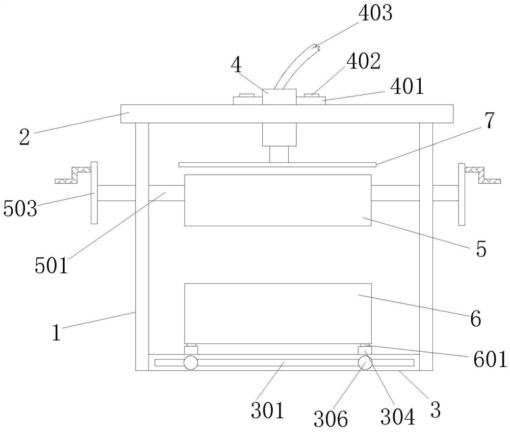
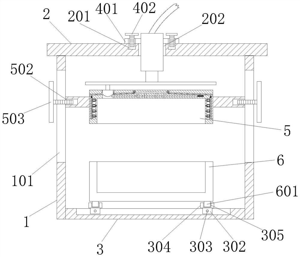
[0036] Such as Figure 1 to Figure 8 As shown, a coated sand casting mold includes a support plate 1, a top plate 2, a bottom plate 3, a jack 4, an upper mold clamp 5, and a lower mold clamp 6, and the outer surface of one side of the support plate 1 is provided with a The chute 101 is movably connected with a threaded rotating disk 503 inside the chute 101, and one side o...


PUM


Abstract

The invention discloses a precoated sand casting mold. The precoated sand casting mold comprises a supporting plate, a top plate, a bottom plate, a jack, an upper mold clamp and a lower mold clamp, wherein a sliding groove is formed in the position, close to the upper end, of the outer surface of one side of the supporting plate; a threaded rotating disc is movably connected in the sliding groove;the side, penetrating the interior of the sliding groove, of the threaded rotating disc is in threaded connection in a third threaded hole formed in a supporting rod; the threaded rotating disc is inthreaded connection in the third threaded hole, and the outer surface of the threaded rotating disc abuts against the outer surface of the supporting rod; the side, away from the sliding groove, of the supporting rod is fixedly connected with the upper mold clamp; and an injection port is formed in the position, close to one side, of the outer surface of the upper end of the upper mold clamp. According to the device, the jack is utilized so that the mounting or dismounting steps during casting can be simplified, and accordingly the yield is increased; and meanwhile, the jack is utilized so that the downward pressing force can be stressed evenly, an inner finished mold is compact, accordingly, the product quality is improved, and losses are reduced.

Description

technical field [0001] The invention relates to the technical field of casting mold devices, in particular to a coated sand casting mold. Background technique [0002] Molds, various molds and tools used in industrial production for injection molding, blow molding, extrusion, die-casting or forging forming, smelting, stamping, etc. to obtain the required products, in short, molds are tools used to make shaped objects , This tool is composed of various parts, and different molds are composed of different parts. It mainly realizes the processing of the shape of the object through the change of the physical state of the formed material, known as the "mother of industry". [0003] 1. The existing device needs to align the upper and lower mold clamps when casting is required and then fix the two. In the traditional fixing, the two are fixed together by using multiple screws, which is not convenient for users to install. Fixing and later disassembly waste time and reduce work eff...

Claims


Application Information

Patent Timeline
Patent Type & Authority Applications(China)
IPC IPC(8): B22D33/04B22C9/02
CPCB22D33/04B22C9/02
Inventor 樊锟方舟
Owner HEBEI HONOR MECHANICAL MOLD
Why Eureka
Try Eureka