Al technical title is built by PatSnap Al team. It summarizes the technical point description of the patent document.
A technology for welding equipment and safety, applied in the field of welding equipment, can solve the problems of reducing the reliability of laser welding equipment, reducing the safety of laser welding equipment, high-temperature spark spattering workers, etc., achieving high practicability, improving practicability, and improving safety effect
Inactive Publication Date: 2021-01-01
西安卧龙网络科技有限公司
View PDF0 Cites 5 Cited by
Summary
Abstract
Description
Claims
Application Information
AI Technical Summary
This helps you quickly interpret patents by identifying the three key elements:
Problems solved by technology
Method used
Benefits of technology
Problems solved by technology
[0003] The existing laser welding equipment will generate a large number of high-temperature sparks during welding, and some of the high-temperature sparks are easy to splash on the staff, thus posing a threat to the personal safety of the staff and reducing the safety of the existing laser welding equipment , Not only that, after the existing laser welding equipment is welded, the temperature of the workpiece will be very high. If the staff directly picks up the workpiece, it is easy to burn the staff, thereby reducing the reliability of the existing laser welding equipment
Method used
Image
Click on the blue label to locate the original text in one second.
Reading with bidirectional positioning of images and text.
Examples
Embodiment Construction
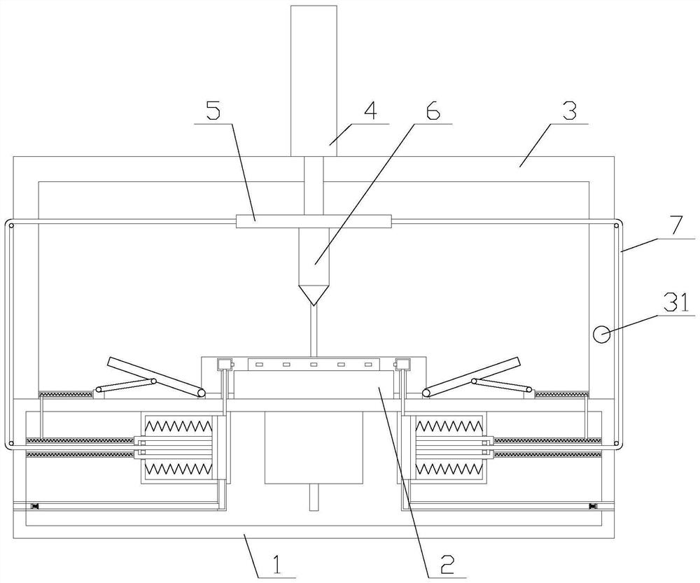
[0026] The present invention is described in further detail now in conjunction with accompanying drawing. These drawings are all simplified schematic diagrams, which only illustrate the basic structure of the present invention in a schematic manner, so they only show the configurations related to the present invention.
[0027] like figure 1 As shown, a welding equipment with high safety includes a base 1, a support frame 3, a cylinder 4, a workbench 2, a lifting plate 5 and a welding device 6, the shape of the support frame 3 is U-shaped, and the support The two ends of the frame 3 are respectively fixedly connected with the two sides above the base 1, the support frame 3 is provided with a through hole, the cylinder body of the cylinder 4 is vertically fixed above the support frame 3, and the cylinder 4 The gas rod passes through the through hole and is fixedly connected with the lifting plate 5, the welding device 6 is arranged below the lifting plate 5, the workbench 2 is...
PUM
Abstract
The invention relates to welding equipment having high safety. The welding equipment comprises a base, a supporting frame, an air cylinder, a workbench, a lifting plate and a welding device and further comprises four cooling mechanisms and four protection mechanisms; each cooling mechanism comprises a fixing box, a driving rope, a driving plate, an air inlet pipe, a filtering screen, a closing assembly, an air outlet pipe, a connecting box, a support, a transmission assembly, two fixing rods and a plurality of first springs; each transmission assembly comprises an annular air bag, a connectingpipe, a power air bag, a third spring, two power plates, two compression rings and a plurality of second springs; each sealing assembly comprises a fixing ring, a sealing plate and a fourth spring; and each protection mechanism comprises a supporting shaft, a protection plate, a hinge rod and a sliding block. According to the welding equipment having the high safety, the function of cooling a workpiece is achieved through the cooling mechanisms, the situations that the temperature of the welded workpiece is too high and a worker is scalded are avoided, the shielding function is achieved through the protection mechanisms, and high-temperature sparks generated in the welding process cannot be splashed to the body of the worker.
Description
technical field [0001] The invention relates to the field of mechanical equipment, in particular to welding equipment with high safety. Background technique [0002] Laser welding is an efficient and precise welding method that uses a high-energy-density laser beam as a heat source. Laser welding is one of the important aspects of the application of laser material processing technology. In the 1970s, it was mainly used for welding thin-walled materials and low-speed welding. The welding process is heat conduction, that is, the laser radiation heats the surface of the workpiece, and the surface heat diffuses to the inside through heat conduction. By controlling the width, energy, peak power and repetition frequency of the laser pulse and other parameters to melt the workpiece and form a specific molten pool. Due to its unique advantages, it has been successfully applied in the precision welding of micro and small parts. [0003] The existing laser welding equipment will ge...
Claims
Application Information
Patent Timeline
Application Date:The date an application was filed.
Publication Date:The date a patent or application was officially published.
First Publication Date:The earliest publication date of a patent with the same application number.
Issue Date:Publication date of the patent grant document.
PCT Entry Date:The Entry date of PCT National Phase.
Estimated Expiry Date:The statutory expiry date of a patent right according to the Patent Law, and it is the longest term of protection that the patent right can achieve without the termination of the patent right due to other reasons(Term extension factor has been taken into account ).
Invalid Date:Actual expiry date is based on effective date or publication date of legal transaction data of invalid patent.